Two-stage drying and pyrolysis sludge disposal, heat energy utilization method and device system
A technology for sludge disposal and sludge, which is applied in pyrolysis sludge treatment, dehydration/drying/concentration sludge treatment, by-product vaporization, etc., can solve the problems of increasing sales costs and achieve increased calorific value and huge social benefits , The effect of solving the problem of sludge treatment
- Summary
- Abstract
- Description
- Claims
- Application Information
AI Technical Summary
Problems solved by technology
Method used
Image

Examples
Embodiment 1)
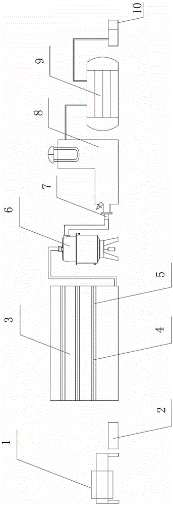
[0030] See figure 1
[0031] The two-stage drying and pyrolysis sludge disposal and heat energy utilization device system are arranged in sequence, including filter press 1, crusher 2, low-temperature and high-speed air-dried sludge drying room 3, and pyrolysis reactor 6, which is a vertical pyrolysis reactor , a combustion chamber 8, a steam generator 9, a waste heat utilization device 10, wherein the discharge port of the low-temperature high-speed air-dried sludge drying room 3 is connected with the feed port of the pyrolysis reactor 6, and the gas outlet on the upper part of the pyrolysis reactor 6 is connected to the The air inlets of the combustion chamber 8 are connected, and the front end of the combustion chamber 8 is provided with a burner 7 . The filter press 1 is a plate-and-frame diaphragm filter press, and a directional air circulation unit is installed on the top of the low-temperature and high-speed air-dried sludge drying room 3 to provide high-speed circulat...
Embodiment 2)
[0039] See figure 1
[0040] The two-stage drying and pyrolysis sludge disposal and heat energy utilization device system are arranged in sequence including filter press 1, crusher 2, low-temperature and high-speed air-dried sludge drying room 3, vertical pyrolysis reactor 6, combustion chamber 8, A steam generator 9 and a waste heat utilization device 10, wherein the outlet of the low-temperature high-speed air-dried sludge drying room 3 is connected to the inlet of the pyrolysis reactor 6, and the gas outlet on the upper part of the pyrolysis reactor 6 is connected to the inlet of the combustion chamber 8. The gas ports are connected, and the front end of the combustion chamber 8 is provided with a burner 7 . The filter press 1 is a plate-and-frame diaphragm filter press, and a directional air circulation unit is installed on the top of the low-temperature and high-speed air-dried sludge drying room 3 to provide high-speed circulating air. There are three layers of laminate...
Embodiment 3)
[0048] See figure 1
[0049] The two-stage drying and pyrolysis sludge disposal and heat energy utilization device system are arranged in sequence including filter press 1, crusher 2, low-temperature and high-speed air-dried sludge drying room 3, vertical pyrolysis reactor 6, combustion chamber 8, A steam generator 9 and a waste heat utilization device 10, wherein the outlet of the low-temperature high-speed air-dried sludge drying room 3 is connected to the inlet of the pyrolysis reactor 6, and the gas outlet on the upper part of the pyrolysis reactor 6 is connected to the inlet of the combustion chamber 8. The gas ports are connected, and the front end of the combustion chamber 8 is provided with a burner 7 . The filter press 1 is a plate-and-frame diaphragm filter press, and a directional air circulation unit is installed on the top of the low-temperature and high-speed air-dried sludge drying room 3 to provide high-speed circulating air. There are three layers of laminate...
PUM
 Abstract
Description
Claims
Application Information
 - R&D
- Intellectual Property
- Life Sciences
- Materials
- Tech Scout
- Unparalleled Data Quality
- Higher Quality Content
- 60% Fewer Hallucinations
Browse by: Latest US Patents, China's latest patents, Technical Efficacy Thesaurus, Application Domain, Technology Topic, Popular Technical Reports.
© 2025 PatSnap. All rights reserved.Legal|Privacy policy|Modern Slavery Act Transparency Statement|Sitemap|About US| Contact US: help@patsnap.com