An automatic welding device and automatic welding method for the assembly of large-scale composite girder steel main girders

A technology of automatic welding and welding methods, applied in the direction of auxiliary equipment, welding equipment, welding equipment, etc., can solve the problems of unsure welding quality consistency, reliability, welding quality influence, etc., and achieve the effect of welding without blind spots

Active Publication Date: 2017-01-04
CHINA RAILWAY BAOJI BRIDGE GRP
View PDF7 Cites 0 Cited by
  • Summary
  • Abstract
  • Description
  • Claims
  • Application Information

AI Technical Summary

Problems solved by technology

At present, manual welding is mostly used for the butt joints of the roof, bottom plate, and web between segments. The welding quality is greatly affected by personal emotions, welding skills, physical conditions, etc., and the consistency and reliability of the welding quality cannot be guaranteed.

Method used


Image

  • An automatic welding device and automatic welding method for the assembly of large-scale composite girder steel main girders
  • An automatic welding device and automatic welding method for the assembly of large-scale composite girder steel main girders
  • An automatic welding device and automatic welding method for the assembly of large-scale composite girder steel main girders

Examples


Embodiment 1

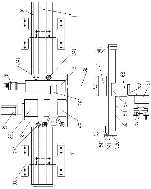
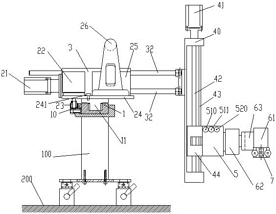
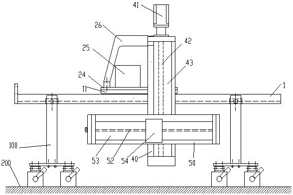
[0026] Embodiment 1: An automatic welding device for the assembly of large-scale composite girder steel main girders. The rack 10 is fixed on one side of the track 1, the trolley 2 is connected to the track slider 11, the track slider 11 is slidingly matched with the track 1, and the reducer 22 is located on the The traveling trolley 2 is driven by the traveling motor 21, the reducer 22 drives the traveling gear 23, the traveling gear 23 matches the rack 12 and drives the traveling trolley 2 to move on the track 1, the traveling trolley 2 is connected with the y-axis adjustment mechanism 3, The y-axis adjustment mechanism 3 is connected to the z-axis adjustment mechanism 4 , the z-axis adjustment mechanism 4 is connected to the x-axis adjustment mechanism 5 , and the x-axis adjustment mechanism 5 is connected to the welding torch clamp 7 .

[0027] figure 1 It is a top view of the orbital welding robot used in the method according to the embodiment of the present invention ins...

Embodiment 2

[0046] Embodiment 2: On the basis of Embodiment 1, a welding method for a large-scale composite girder steel main girder assembly automatic welding device, the two workpieces to be welded are butted and a groove is formed, and an orbital welding robot is installed on the groove. On the corresponding track 1, the track-type welding robot includes a walking trolley 2 capable of moving on the track 1, an adjustment assembly and a welding torch clamp 7 with a welding torch installed, and the adjustment assembly includes a y-axis connected to the walking trolley 2 An adjustment mechanism 3; a z-axis adjustment mechanism 4 connected to the y-axis adjustment mechanism 3; an x-axis adjustment mechanism 5 connected to the z-axis adjustment mechanism 4, and the x-axis adjustment mechanism 5 is connected to the welding torch clamp 7 and the controller 25 for controlling the walking dolly and the adjustment assembly, the controller 25 controls the walking dolly 2 to move along the track 1,...


PUM


Abstract

The invention relates to an automatic welding device and an automatic welding method for large-scale composite girder steel main girder assembly that can realize no blind area in the welding seam direction and is used for automatic welding of large composite girder steel main girder. The rack is fixed on one side of the track, and the walking trolley and track slider Connection, the track slider and the track slide and cooperate, the reducer is located on the traveling trolley and is driven by the traveling motor, the reducer drives the traveling gear, the traveling gear matches the rack and drives the traveling trolley to move on the track, the walking trolley and the y-axis are adjusted The mechanism is connected, the y-axis adjustment mechanism is connected with the z-axis adjustment mechanism, the z-axis adjustment mechanism is connected with the x-axis adjustment mechanism, and the x-axis adjustment mechanism is connected with the welding torch clamp.

Description

technical field [0001] The invention relates to an automatic welding device and an automatic welding method for the assembly of large composite girder steel main girders, which can realize no blind area in the welding seam direction and is used for automatic welding of large composite girder steel main girders, and belongs to the field of special welding equipment manufacturing. Background technique [0002] In recent years, large-scale composite beams have been widely used due to their excellent comprehensive performance, and the ring joints between segments of the steel main girder assembly are one of the most important welds, and the number is relatively large. At present, manual welding is mostly used for butt joints of the roof, bottom and web between segments. The welding quality is greatly affected by personal emotions, welding skills, physical conditions, etc., and the consistency and reliability of the welding quality cannot be guaranteed. Contents of the invention...

Claims


Application Information

Patent Timeline
Patent Type & Authority Patents(China)
IPC IPC(8): B23K31/02
CPCB23K37/0211B23K37/0252B23K37/0294B23K2101/28
Inventor 李军平车平成宇海刘治国朱新华刘雷吴小兵薛龙邹勇
Owner CHINA RAILWAY BAOJI BRIDGE GRP
Why Eureka
Try Eureka