


Quick Research
Generate reliable direction feasibility study reports for your R&D in just a few steps.

Technical Q&A
Discover and master advanced knowledge NOW. Basics, ideas, possibilities, all at once.

Find Solutions
As an expert in R&D theories, this can generate solutions to your technical problems instantly.

Evaluate Feasibility
Analyze your overall solution with one click, know your potential R&D risks in advance.

Monitor Landscape
Get weekly tech updates, stay abreast of the latest tech innovations and key insights.
Large combined joist steel girder assembling automatic welding device and automatic welding method
A technology of automatic welding and welding methods, applied in the direction of auxiliary equipment, welding equipment, welding equipment, etc., can solve the problems of unsure welding quality consistency, reliability, welding quality influence, etc., and achieve the effect of welding without blind spots
- Summary
- Abstract
- Description
- Claims
- Application Information
AI Technical Summary
Problems solved by technology
Method used
Image


Examples
Embodiment 1
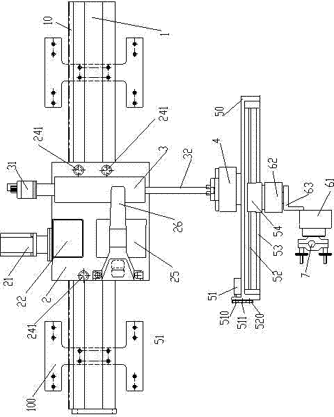
[0026] Embodiment 1: An automatic welding device for the assembly of large-scale composite girder steel main girders. The rack 10 is fixed on one side of the track 1, the trolley 2 is connected to the track slider 11, the track slider 11 is slidingly matched with the track 1, and the reducer 22 is located on the The traveling trolley 2 is driven by the traveling motor 21, the reducer 22 drives the traveling gear 23, the traveling gear 23 matches the rack 12 and drives the traveling trolley 2 to move on the track 1, the traveling trolley 2 is connected with the y-axis adjustment mechanism 3, The y-axis adjustment mechanism 3 is connected to the z-axis adjustment mechanism 4 , the z-axis adjustment mechanism 4 is connected to the x-axis adjustment mechanism 5 , and the x-axis adjustment mechanism 5 is connected to the welding torch clamp 7 .
[0027] figure 1 It is a top view of the orbital welding robot used in the method according to the embodiment of the present invention ins...
Embodiment 2
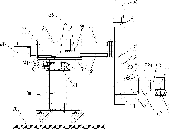
[0046] Embodiment 2: On the basis of Embodiment 1, a welding method for a large-scale composite girder steel main girder assembly automatic welding device, the two workpieces to be welded are butted to form a groove, and the orbital welding robot is installed on the groove. On the corresponding track 1, the track-type welding robot includes a walking trolley 2 capable of moving on the track 1, an adjustment assembly and a welding torch clamp 7 with a welding torch installed, and the adjustment assembly includes a y-axis connected to the walking trolley 2 An adjustment mechanism 3; a z-axis adjustment mechanism 4 connected to the y-axis adjustment mechanism 3; an x-axis adjustment mechanism 5 connected to the z-axis adjustment mechanism 4, and the x-axis adjustment mechanism 5 is connected to the welding torch clamp 7 and the controller 25 for controlling the walking dolly and the adjustment assembly, the controller 25 controls the walking dolly 2 to move along the track 1, and ...
PUM
 Abstract
Description
Claims
Application Information
 - R&D Engineer
- R&D Manager
- IP Professional
- Industry Leading Data Capabilities
- Powerful AI technology
- Patent DNA Extraction
Browse by: Latest US Patents, China's latest patents, Technical Efficacy Thesaurus, Application Domain, Technology Topic, Popular Technical Reports.
© 2024 PatSnap. All rights reserved.Legal|Privacy policy|Modern Slavery Act Transparency Statement|Sitemap|About US| Contact US: help@patsnap.com