Anti-bending Medical Surgical Soft Tissue Expander

A soft tissue and dilator technology, applied in the field of medical devices, can solve the problems of deformation of the main rod and affect the use effect, etc., and achieve the effect of solving large force, reducing the amount of use, and preventing falling off

Active Publication Date: 2016-08-31
钱建民
View PDF5 Cites 0 Cited by
  • Summary
  • Abstract
  • Description
  • Claims
  • Application Information

AI Technical Summary

Problems solved by technology

[0004] The purpose of the present invention is to design a bending-resistant medical surgical soft tissue that greatly improves the bending resistance without increasing the size of the main rod in order to solve the problem that the main rod of the retractor is greatly affected by the tensile deformation. dilator

Method used


Image

  • Anti-bending Medical Surgical Soft Tissue Expander
  • Anti-bending Medical Surgical Soft Tissue Expander
  • Anti-bending Medical Surgical Soft Tissue Expander

Examples


Embodiment 1

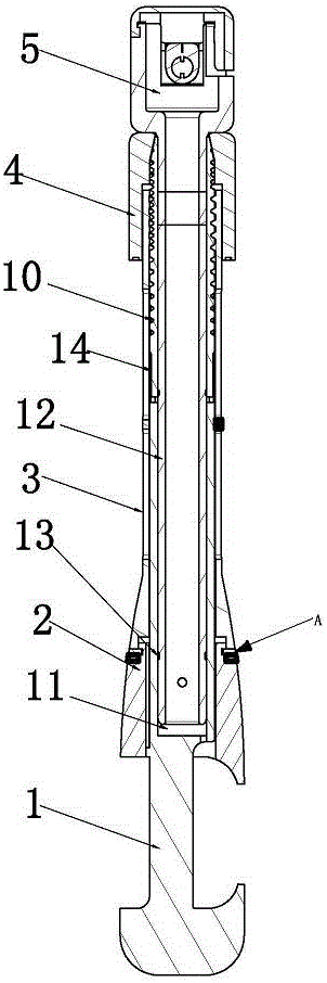
[0028] Such as Figure 2-6 shown.

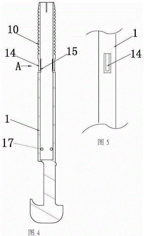
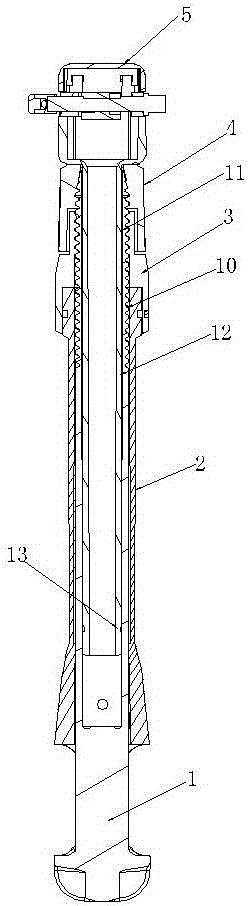
[0029] A bending-resistant medical surgical soft tissue expander, which includes a main rod 1, a locking sleeve 2, a locking operating member 3, a belt take-up device lock sleeve 4, a belt take-up device 5 and a hook plate 6, such as figure 2 As shown, the lower end of the main rod 1 is provided with a half dovetail groove matching the side of the operating bed, and its upper end is provided with an external thread 10 and a socket 11. The upper end of the external thread 10 has a tapered structure and is axially There is an opening, the locking sleeve 2 is set on the main rod 1, and the other half of the dovetail groove that can move up and down is provided at the lower end, and the upper end surface of the locking sleeve 2 is offset against the lower end surface of the locking operation part 3 and can be used as a relative The locking operation part 3 is screwed on the external thread 10 on the upper end of the main rod 1, and the locking...

Embodiment 2

[0033] Such as Figure 7 shown.

[0034] The difference between this embodiment and the first embodiment is that an anti-bending reinforcing rod 16 is added in the center of the main rod 1 to further enhance the bending resistance of the main rod. The anti-bending reinforcing rod 16 can be inserted into the insertion rod at the lower end of the take-up device 5 12, in order to facilitate the insertion of the insertion rod 12 on the anti-bending reinforcement rod 16, the lower end of the insertion rod 12 should also be provided with a vent hole 18 ( image 3 ).

[0035] Working process of the present invention is:

[0036] one. Lifting device installation.

[0037] First turn the locking operation part 3 so that the opening of the dovetail groove is larger than the thickness of the fixed guide rail at the side of the operating bed, then align the dovetail groove with the side of the operating bed and insert, then turn the locking operation part 3 close to the locking sleeve...


PUM


Abstract

An anti-bending medical surgery soft tissue expander comprises a main rod (1), a locking sleeve (2), a locking operation piece (3), a band collecting device locking sleeve (4) and a band collecting device (5). One half dovetail groove is formed in the lower end of the main rod (1), and an external thread (10) with an opening and an inserting hole (11) are formed in the upper end of the main rod (1). The anti-bending medical surgery soft tissue expander is characterized in that the main rod (1) is sleeved with the locking sleeve (2), the other half dovetail groove capable of moving up and down is formed in the lower end of the locking sleeve, the upper end face of the locking sleeve (2) and the lower end face of the locking operation piece (3) abut against each other and are connected into a whole in a relative rotating mode, and the locking operation piece (3) is arranged on the external thread (10) at the upper end of the main rod (1) in a rotating mode; the band collecting device locking sleeve (4) and the locking operation piece (3) are sequentially mounted on the external thread (10) at the upper end of the main rod (1), and the locking sleeve (2) and the dovetail groove formed in the lower end of the locking sleeve are integrally connected. The anti-bending medical surgery soft tissue expander is good in anti-bending performance and convenient to operate and use.

Description

technical field [0001] The invention relates to a medical device, especially a retractor used in surgery that can replace the manual retraction of the incision so that the surgical field can be fully exposed, specifically a bending-resistant retractor suitable for various operations. Type medical surgical soft tissue expander. Background technique [0002] At present, in operations with open abdominal incisions, such as general surgery, hepatobiliary surgery, and obstetrics and gynecology, in order to obtain an ideal surgical field, it is necessary to keep the opened abdomen well retracted; the existing methods mainly rely on surgical assistants Pulling the incision apart with pull hooks from both sides is ineffective and labor-intensive. People have invented various abdominal operation retractors to replace artificial traction for this reason, and people are liberated from heavy physical labor, and obtained better use effect. The invention patents with the application num...

Claims


Application Information

Patent Timeline
Patent Type & Authority Patents(China)
IPC IPC(8): A61B17/02
CPCA61B17/02
Inventor 钱建民
Owner 钱建民
Why Eureka
Try Eureka