Movement instrument for cervical vertebra rehabilitation
A technology of exercise equipment and cervical spine, applied in sports accessories, passive exercise equipment, gymnastics equipment, etc., to achieve the effect of functional recovery and enhancement, and curing cervical spondylosis
- Summary
- Abstract
- Description
- Claims
- Application Information
AI Technical Summary
Problems solved by technology
Method used
Image
Examples
Embodiment 1
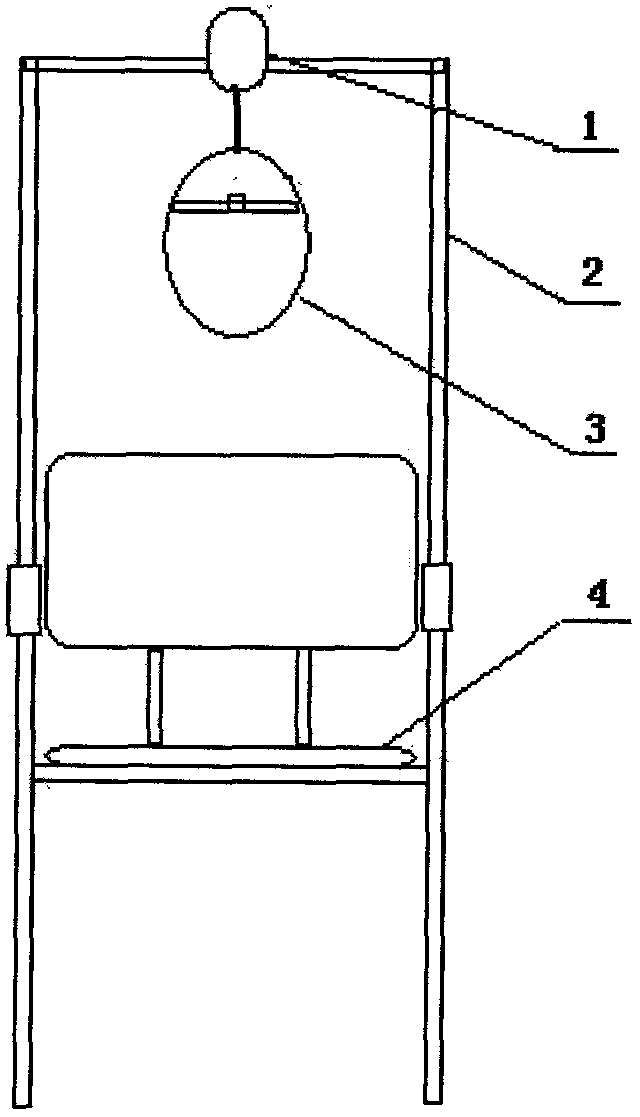
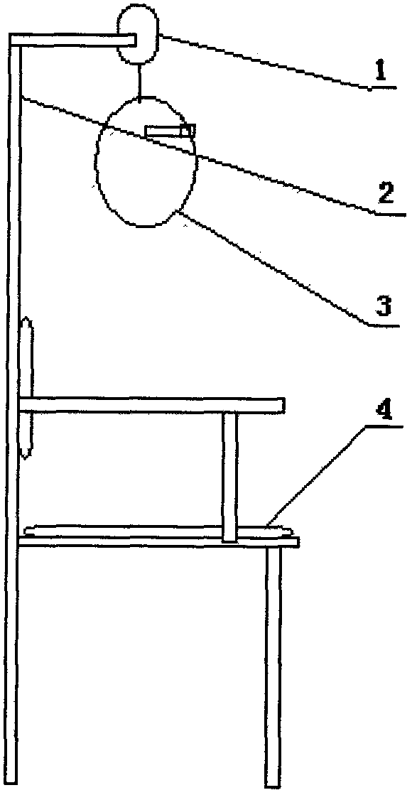
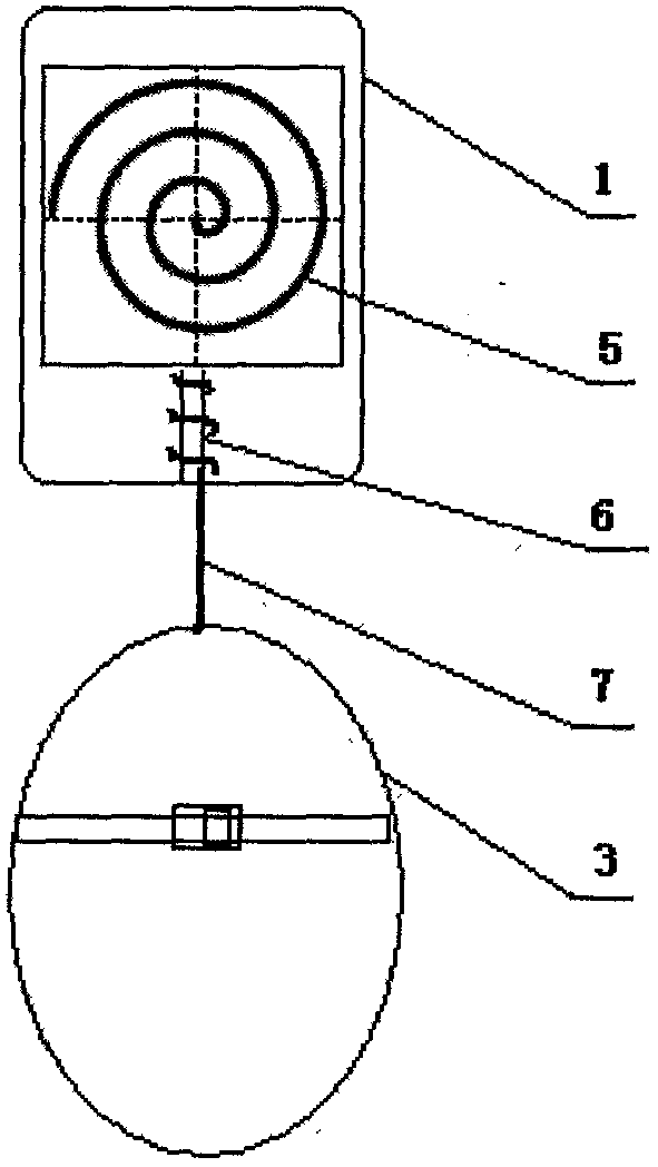
[0017] Depend on figure 1 , figure 2 As shown, the cervical spine rehabilitation exerciser includes a seat 4 and a support 2, the upper end of the support 2 is fixed with a damping tractor 1, and a horizontally placed volute spring 5 is fixed in the damping traction 1 (see image 3 ), the central position of the spring has a connecting rod 6 perpendicular to it, the connecting rod 6 is connected and wrapped with a traction line 7, the end of the traction line 7 is connected with a head fixing device 3, and the head fixing device 3 is suspended on the seat above the chair.
[0018] Depend on Figure 5 As shown, the head immobilization device has a head fixation belt 9, which is used to fix the patient's head, and is connected with a support belt 10 which can respectively pull the patient's mandibular support belt 11 and the occiput, the fixation belt 9 and the support belt 9. Bands 10 and 11 are adjustable to suit patients with different head diameters.
[0019] The patien...
Embodiment 2
[0022] Depend on figure 1 , figure 2 As shown, the cervical spine rehabilitation exercise device includes a seat 4 and a support 2, the upper end of the support is fixed with a damping tractor 1, and a spring is fixed inside the damping traction 1, and the spring is connected with a traction line 7, and the end of the traction line is connected with a head Head fixture 3, the head fixture 3 is hung above the seat.
[0023] Depend on Figure 5 As shown, the head immobilization device has a head fixation belt 9, which is used to fix the patient's head, and is connected with a support belt 10 which can respectively pull the patient's mandibular support belt 11 and the occiput, the fixation belt 9 and the support belt 9. Bands 10 and 11 are adjustable to suit patients with different head diameters.
[0024] The patient sits on the seat, the forehead is fixed with a fixed belt, and the mandible and occiput are respectively placed on the front and rear pull belts to produce a mo...
Embodiment 3
[0026] Depend on figure 1 , figure 2 As shown, the cervical spine rehabilitation exercise device includes a seat 4 and a support 2, the upper end of the support is fixed with a damping tractor 1, and a latex tape is fixed in the damping traction 1, and the bottom of the latex tape is connected with a traction line 7, and the end of the traction line Connected with the head fixing device 3, the head fixing device 3 is hung above the seat.
[0027] Depend on Figure 5 As shown, the head immobilization device has a head fixation belt 9, which is used to fix the patient's head, and is connected with a support belt 10 which can respectively pull the patient's mandibular support belt 11 and the occiput, the fixation belt 9 and the support belt 9. Bands 10 and 11 are adjustable to suit patients with different head diameters.
[0028] The patient sits on the seat, the forehead is fixed with a fixed belt, and the mandible and occiput are respectively placed on the front and rear pu...
PUM
 Abstract
Description
Claims
Application Information
 - R&D
- Intellectual Property
- Life Sciences
- Materials
- Tech Scout
- Unparalleled Data Quality
- Higher Quality Content
- 60% Fewer Hallucinations
Browse by: Latest US Patents, China's latest patents, Technical Efficacy Thesaurus, Application Domain, Technology Topic, Popular Technical Reports.
© 2025 PatSnap. All rights reserved.Legal|Privacy policy|Modern Slavery Act Transparency Statement|Sitemap|About US| Contact US: help@patsnap.com


