Field emission light source, decoration lamp containing field emission light source, and decoration lamp assembly

A field emission and decorative lamp technology, applied in the direction of fluorescent screen lamps, lamp parts, etc., can solve the problems of complex structure and complicated manufacturing process, and achieve the effect of soft light

Inactive Publication Date: 2014-06-04
OCEANS KING LIGHTING SCI&TECH CO LTD +2
View PDF0 Cites 0 Cited by
  • Summary
  • Abstract
  • Description
  • Claims
  • Application Information

AI Technical Summary

Problems solved by technology

However, in order to achieve a better decorative effect for the light decorative lamps currently on the market, usually the structure of this kind of decorative lamps is relatively complicated, and its manufacturing process is also relatively complicated.

Method used


Image

  • Field emission light source, decoration lamp containing field emission light source, and decoration lamp assembly
  • Field emission light source, decoration lamp containing field emission light source, and decoration lamp assembly
  • Field emission light source, decoration lamp containing field emission light source, and decoration lamp assembly

Examples


Embodiment Construction

[0029] In order to facilitate the understanding of the present invention, the present invention will be described more fully below with reference to the associated drawings. Preferred embodiments of the invention are shown in the accompanying drawings. However, the present invention can be embodied in many different forms and is not limited to the embodiments described herein. On the contrary, the purpose of providing these embodiments is to make the disclosure of the present invention more thorough and comprehensive.

[0030] It should be noted that when an element is referred to as being “fixed” to another element, it can be directly on the other element or there can also be an intervening element. When an element is referred to as being "connected to" another element, it can be directly connected to the other element or intervening elements may also be present. The terms "vertical," "horizontal," "left," "right," and similar expressions are used herein for purposes of ill...


PUM


Abstract

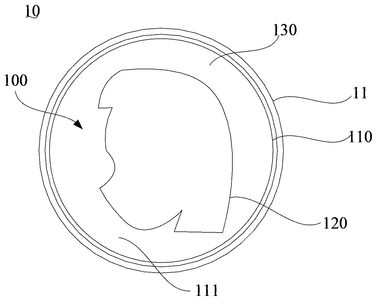
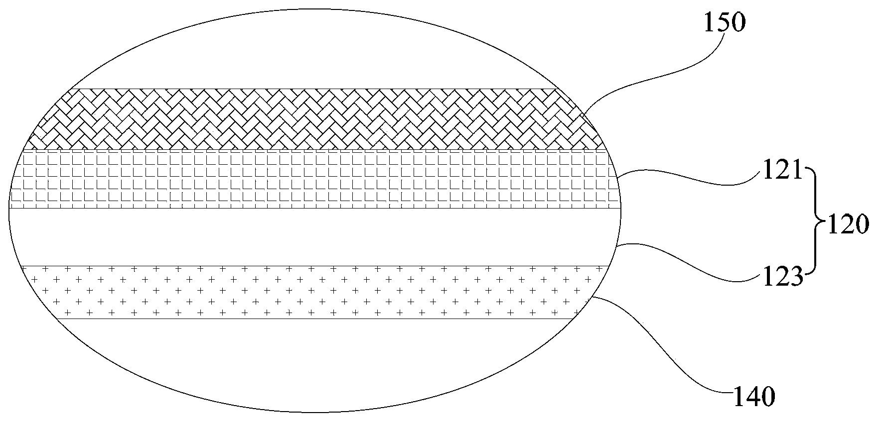
Provided is a field emission light source which comprises a cathode layer, an anode layer, a gas emission layer and a light emission layer. The cathode layer presents to be an enclosed curved surface structure, and a sealing cavity is formed by the cathode layer via enclosing. The anode layer presents to be the enclosed curved surface structure and is accommodated in the sealing cavity. The anode layer and the cathode layer are opposite in arrangement and are spaced by preset distance. The sealing cavity is filled by gas which is arranged between the cathode layer and the anode layer so that the gas emission layer is formed, and electrons can be ionized from the gas emission layer. The light emission layer is attached to the anode layer and is opposite to the cathode layer in arrangement. The light emission layer is impacted by the electrons emitted by the gas emission layer so that visible light is generated. The three-dimensional light emission effect can be realized by the field emission light source so that the field emission light source is simple in structure and easy to manufacture, and more natural and lifelike decoration effect can be realized. Besides, the invention also provides a decoration lamp and a decoration lamp assembly.

Description

technical field [0001] The invention relates to a lighting device, in particular to a field emission light source, a decorative lamp containing the field emission light source and a decorative lamp assembly. Background technique [0002] With the progress of society and the improvement of people's living standards, the role of lighting in the architectural environment is increasing day by day, and lighting design has become an important part of architectural design. At present, great changes have taken place in both lighting design concepts and lighting equipment. The new design concept emphasizes people-oriented humanized design to meet people's multiple requirements such as beautiful environment, appropriate brightness, comfortable space layering, and rich three-dimensional sense. At the same time, it pays attention to artistry, cultural taste and characteristics. Lighting is no longer simply lighting up the lights in the traditional sense, but to use the special "langua...

Claims


Application Information

Patent Timeline
Patent Type & Authority Applications(China)
IPC IPC(8): H01J63/06H01J63/02
Inventor 周明杰徐习贤陈贵堂
Owner OCEANS KING LIGHTING SCI&TECH CO LTD
Why Eureka
Try Eureka