


Quick Research
Generate reliable direction feasibility study reports for your R&D in just a few steps.

Technical Q&A
Discover and master advanced knowledge NOW. Basics, ideas, possibilities, all at once.

Find Solutions
As an expert in R&D theories, this can generate solutions to your technical problems instantly.

Evaluate Feasibility
Analyze your overall solution with one click, know your potential R&D risks in advance.

Monitor Landscape
Get weekly tech updates, stay abreast of the latest tech innovations and key insights.
Residual quantity reduction member
A technology for components and margins, applied in the field of margin reduction components, can solve the problems of increased residual volume, guidance, and reduced residual content of contents, and achieves the effect of smooth discharge and increased volume
- Summary
- Abstract
- Description
- Claims
- Application Information
AI Technical Summary
Problems solved by technology
Method used
Image

Examples
Embodiment 1
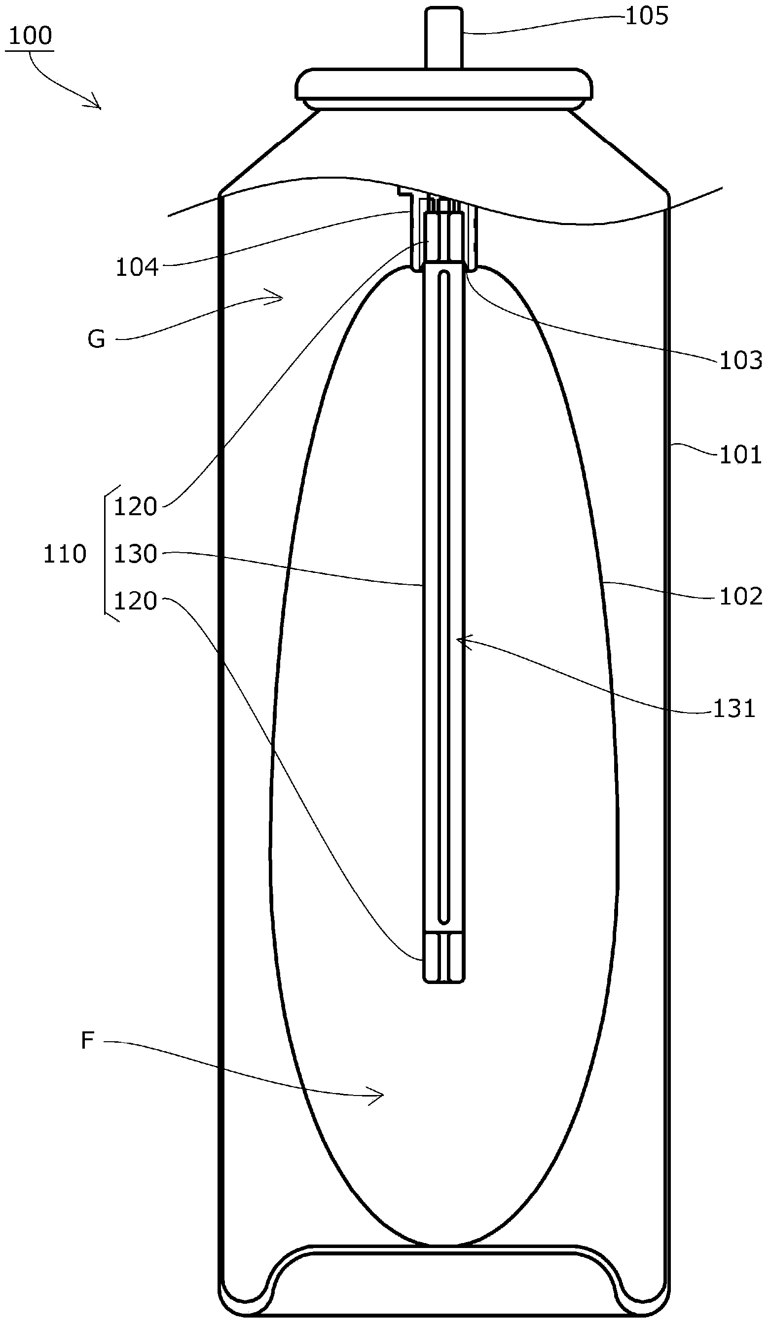
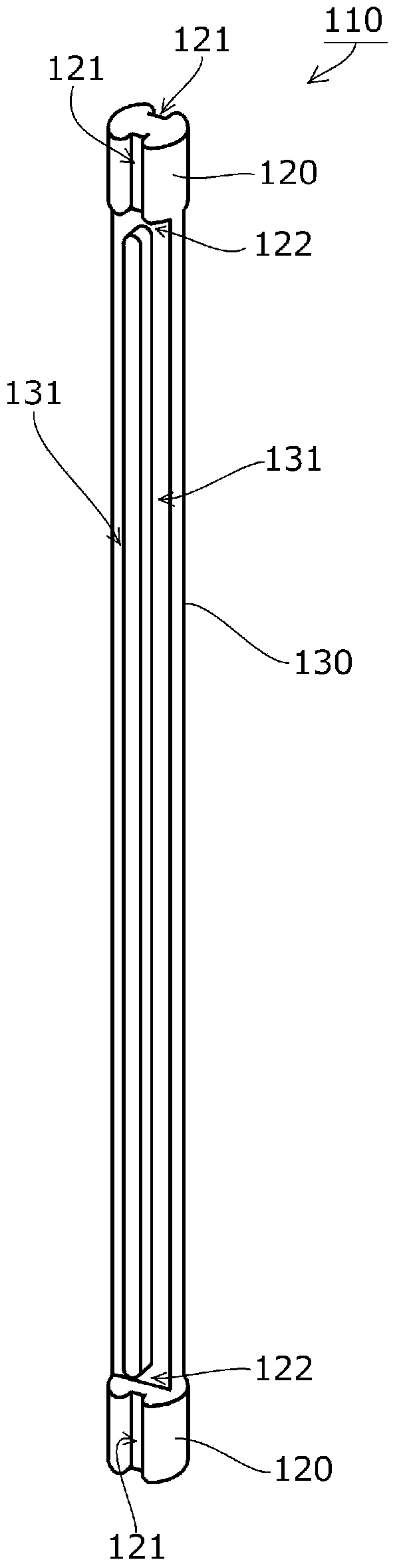
[0065] The remaining amount reducing member 110 according to the first embodiment of the present invention is inserted into the inflow port 103 of the spray container 100 similar to the above-mentioned known spray container 500 instead of the known insertion tube 511 .
[0066] That is, if figure 1 As shown, inside the outer tank 101 of the spray container 100, an inner bag 102 for storing the contents F is provided, and the inner bag 102 is provided with a spout 104 having a rod 105 at the top and an inflow port 103 opening to the inside.
[0067] The structure is such that the space between the outer tank 101 and the inner bag 102 of the spray container 100 is filled with pressurized fluid G such as nitrogen gas, and when the lever 105 is pressed, the contents contained in the inner bag 102 flow in from the inlet 103 and flow from the lever 105. The top of the discharges outwards.
[0068] Then, the remaining amount reducing member 110 according to the first embodiment of ...
Embodiment 2
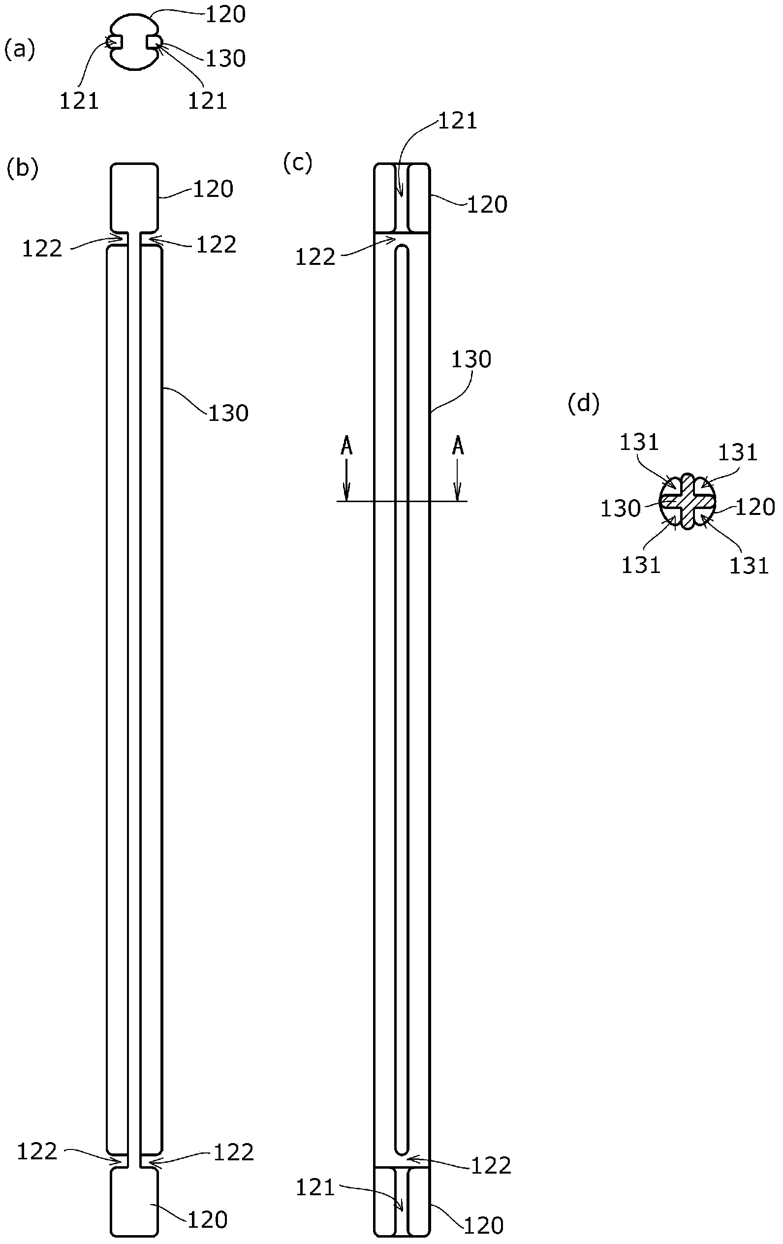
[0085] Such as Figure 4 , Figure 5 As shown, the margin reducing member 210 as the second embodiment of the present invention replaces the structure of the margin reducing member 110 of the first embodiment, and an overlapping preventing portion 240 is provided at the middle position of the guide portion 230 in the longitudinal direction.
[0086] That is, the remaining amount reducing member 210 according to the second embodiment of the present invention is formed of a solid rod-shaped body, and includes attachment portions 220 that can be attached to both ends so that the content F can flow into the inlet 103 of the inner bag 102. , and a guide portion 230 formed with a plurality of guide grooves 231 in the longitudinal direction of the outer periphery, and an end groove 222 perpendicular to the longitudinal direction is formed between the mounting portion 220 and the guide portion 230 .
[0087] The guide groove 231 provided in the longitudinal direction of the guide par...
Embodiment 3
[0099] Such as Figure 6 , Figure 7 As shown, the remaining amount reducing member 310 according to the third embodiment of the present invention is composed of a solid rod-shaped body, and has mounting parts that can be mounted on both ends so that the content F can flow into the inflow port 103 of the inner bag 102. 320, and a guide portion 330 formed with a plurality of guide grooves 331 in the longitudinal direction of the outer periphery.
[0100] In addition, in this embodiment, the end grooves 122 , 222 as in the first and second embodiments are not formed between the mounting portion 320 and the guide portion 330 .
[0101] The guide grooves 331 provided in the longitudinal direction of the guide part 330 are configured as follows: the cross-sectional shape is V-shaped at an included angle of 90° and arranged at intervals of 90° along the circumferential direction of the outer periphery. cruciform.
[0102] The end surface 323 of the mounting part 320 is formed in ...
PUM
 Abstract
Description
Claims
Application Information
 - R&D Engineer
- R&D Manager
- IP Professional
- Industry Leading Data Capabilities
- Powerful AI technology
- Patent DNA Extraction
Browse by: Latest US Patents, China's latest patents, Technical Efficacy Thesaurus, Application Domain, Technology Topic, Popular Technical Reports.
© 2024 PatSnap. All rights reserved.Legal|Privacy policy|Modern Slavery Act Transparency Statement|Sitemap|About US| Contact US: help@patsnap.com