
a slicer

A slicer and slicing device technology, which is applied in metal processing and other directions, can solve problems such as poor taste, loss of nutrients, and high extrusion force of food materials, so as to avoid molecular structure damage, less loss of nutrients, and small extrusion force Effect

Active Publication Date: 2015-09-09
TIANJIN RES INST FOR ADVANCED EQUIP TSINGHUA UNIV
View PDF9 Cites 0 Cited by
  • Summary
  • Abstract
  • Description
  • Claims
  • Application Information

AI Technical Summary

Problems solved by technology

However, when this kind of slicing is cut, the extrusion force of the knife on the ingredients is large, which easily destroys the molecular structure of the ingredients, resulting in poor taste and loss of nutrients.
In addition, if the existing slicer needs to cut the blocky food into filaments, the blocky food is usually sent to the feed end of the slicer, and then cut into slices by a slicer, and the slices are collected at the discharge end of the slicer. , and then the slices are fed from the feeding end of the slicer, and the slices are cut into filaments through the slicer device. The operation process is cumbersome and the efficiency is low.

Method used


Image

  • a slicer
  • a slicer
  • a slicer

Examples


Embodiment 1

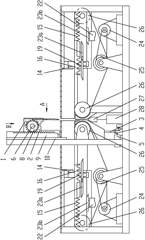
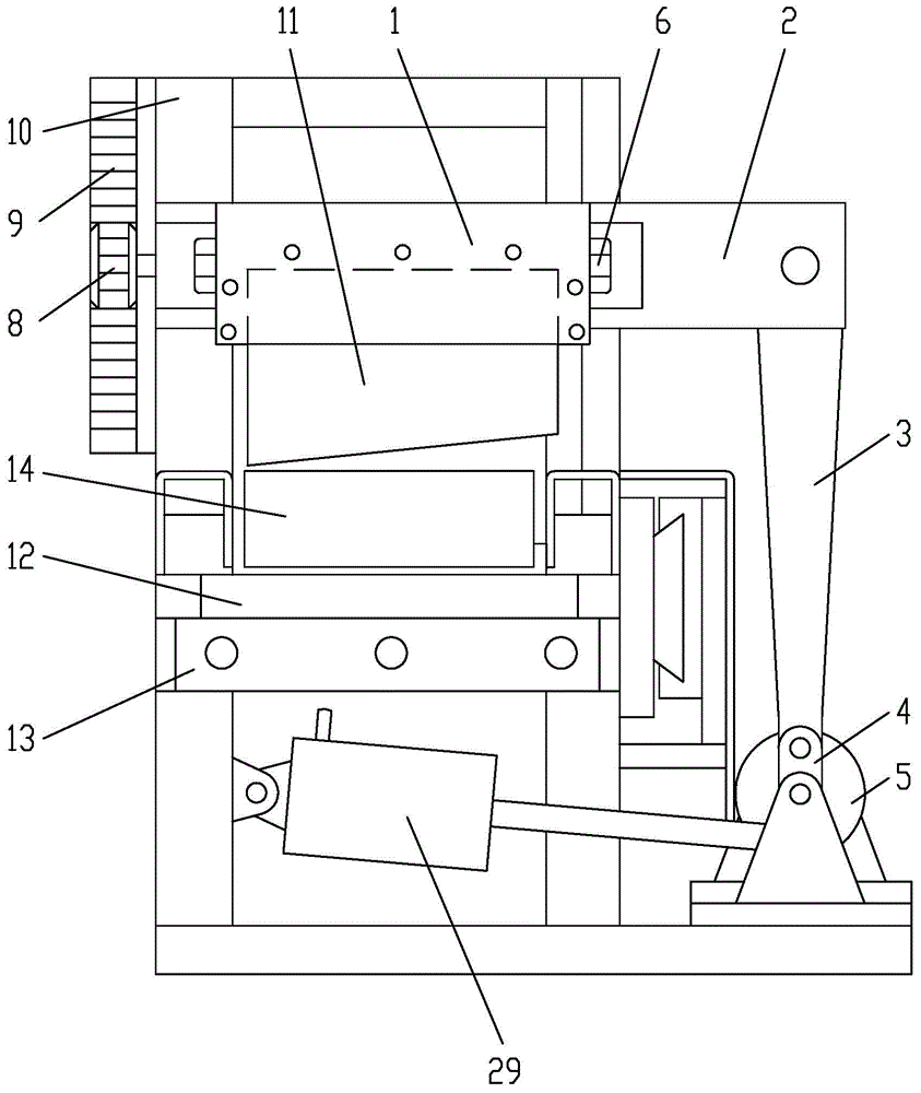
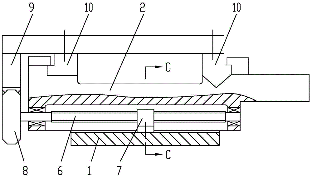
[0025] Example 1, see figure 1 , figure 2 , image 3 , Figure 4 , Figure 5 , Figure 8 , a slicing machine, including a slicing device and a control system, the slicing device includes a vertical guide rail pair, a horizontal guide rail pair and a cutter mounting seat 1, and the vertical guide rail pair is composed of a triangular guide rail and a rectangular guide rail to form a combined guide rail pair The closed guide rail structure, the horizontal guide rail pair is a dovetail guide rail pair, and an adjustable insert 2a is provided between the cutter mounting seat 1 and the matching dovetail structure of the horizontal support guide rail 2 to adjust the gap of the matching dovetail structure. Ensure that the cutter mounting seat 1 moves smoothly; the cutter mounting seat 1 is fixedly connected with a movable blade 11 with an inclined edge, and when the movable blade 11 cuts and feeds, the edge of the movable blade 11 is installed toward the cutter The horizontal m...

Embodiment 2

[0030] Example 2, see Image 6 , the locking mechanism includes a movable tongue 19 and a fixed tongue 20 arranged on the auxiliary moving guide rail of the third linear guide rail, and the movable tongue 19 and the fixed tongue 20 form a caliper shape; the movable tongue 19 is located in the horizontal section Below, there is a part of the caliper that stretches into the movable stop tongue 19 and the fixed stop tongue 20 on the width direction of the horizontal section of the conveyor belt 16; Sliding fit structure, a tongue spring 21 is connected between the movable tongue 19 and the chute bottom of the auxiliary moving guide rail of the third linear guide rail, and the tongue spring 21 is used to keep the movable tongue 19 away from the conveying belt in the height direction 16 horizontal sections, the other side of the movable tongue 19 is provided with a push rod electromagnet 22, and the push rod electromagnet 22 is used to push the movable tongue 19 toward the fixed to...


PUM


Abstract

The invention discloses a slicing machine which comprises a slicing device and a control system. The slicing device comprises a vertical guide rail pair, a horizontal guide rail pair and a cutter installation base used for containing a movable blade. The cutter installation base forms a movable guide rail portion of the horizontal guide rail pair. A horizontal supporting guide rail of the horizontal guide rail pair forms a movable guide rail portion of the vertical guide rail pair. The horizontal supporting guide rail is driven by a cutter driving motor to move up and down in a reciprocating mode. The cutter installation base forms horizontal shuttling motion through a lead screw and nut pair and a gear and rack structure in the process that the horizontal supporting guide rail moves up and down in the reciprocating mode. The feeding end and the discharging end of the slicing device are respectively connected with a belt conveyer. The control system is provided with a control unit respectively used for controlling the conveying directions and speeds of the two belt conveyers. The slicing machine has the advantages that the molecular structure formed after food materials are cut is complete, the nutritive value of the food materials is high, and the taste is good; the operation of shredding the blocky food materials is convenient, and cutting efficiency is high.

Description

technical field [0001] The patent of the present invention relates to a kitchen facility, in particular to a slicer for cutting block-shaped food materials into slices or shreds. Background technique [0002] Slicer is a kitchen vegetable cutting equipment that cuts food materials into slices or filaments. Compared with traditional manual vegetable cutting, it has the advantages of fast cutting speed, high efficiency and low labor intensity. Therefore, the slicer is more and more widely used in the field of modern kitchen or food material processing. Most of the existing slicers use blade rotation for cutting, which has high cutting speed and high efficiency, and is especially widely used in the field of food material processing. However, when this kind of slicing is cut, the extrusion force of the knife on the food material is large, which easily destroys the molecular structure of the food material, resulting in poor taste and loss of nutrients. In addition, if the exist...

Claims


Application Information

Patent Timeline
Patent Type & Authority Patents(China)
IPC IPC(8): B26D1/01B26D7/06B26D7/32B26D7/26B26D5/14
Inventor 谭明
Owner TIANJIN RES INST FOR ADVANCED EQUIP TSINGHUA UNIV
Learn More