Chair

A technology of chairs and long holes, applied in the field of chairs, can solve the problem of low degree of freedom of elastic deformation

Inactive Publication Date: 2014-05-21
KOKUYO CO LTD
View PDF7 Cites 11 Cited by
  • Summary
  • Abstract
  • Description
  • Claims
  • Application Information

AI Technical Summary

Problems solved by technology

[0003] However, most of the conventional backrests have holes formed in the shape of a substantially equal-width rectangle or a simple round hole shape, and the degree of freedom in design for imparting elastic deformation is low.

Method used


Image

  • Chair
  • Chair
  • Chair

Examples


Embodiment Construction

[0033] Below, refer to Figure 1-12 One embodiment of the present invention will be described.

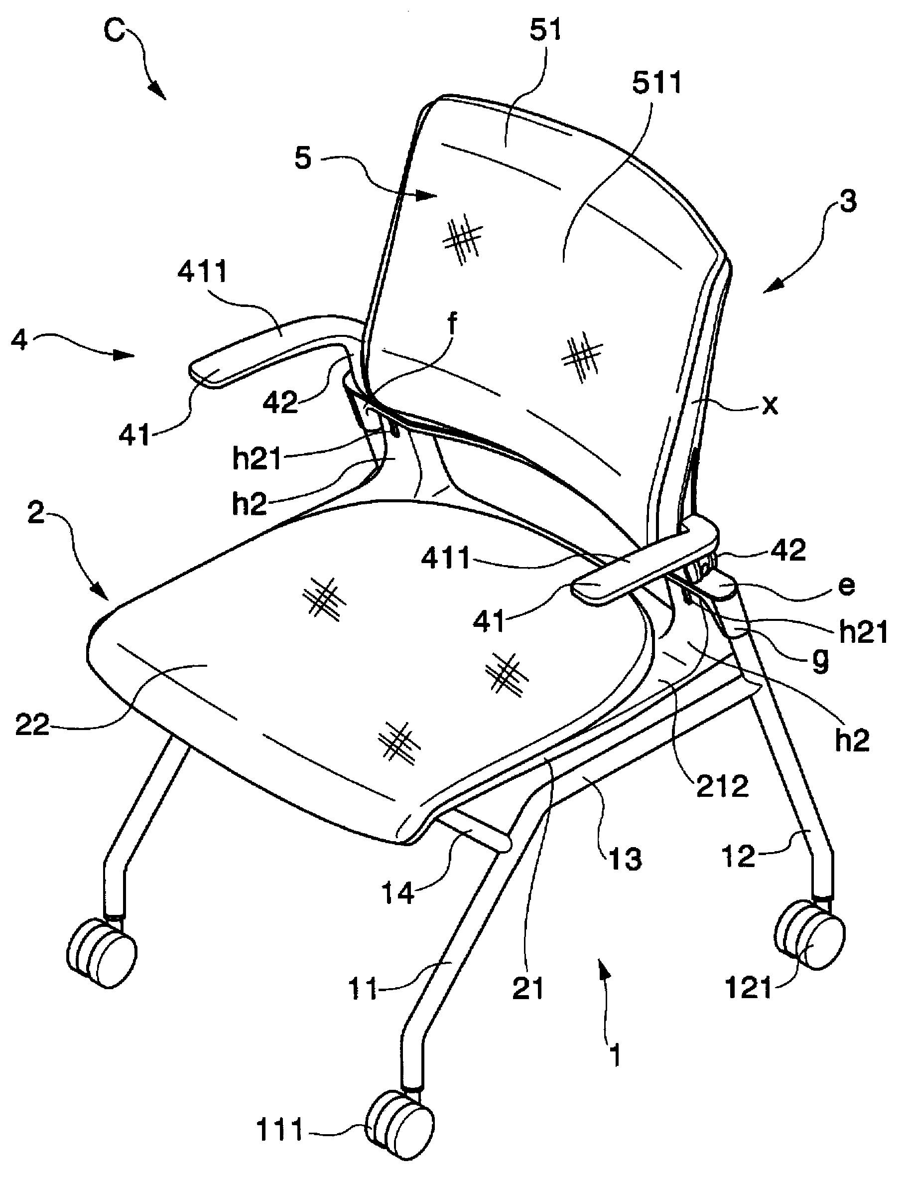
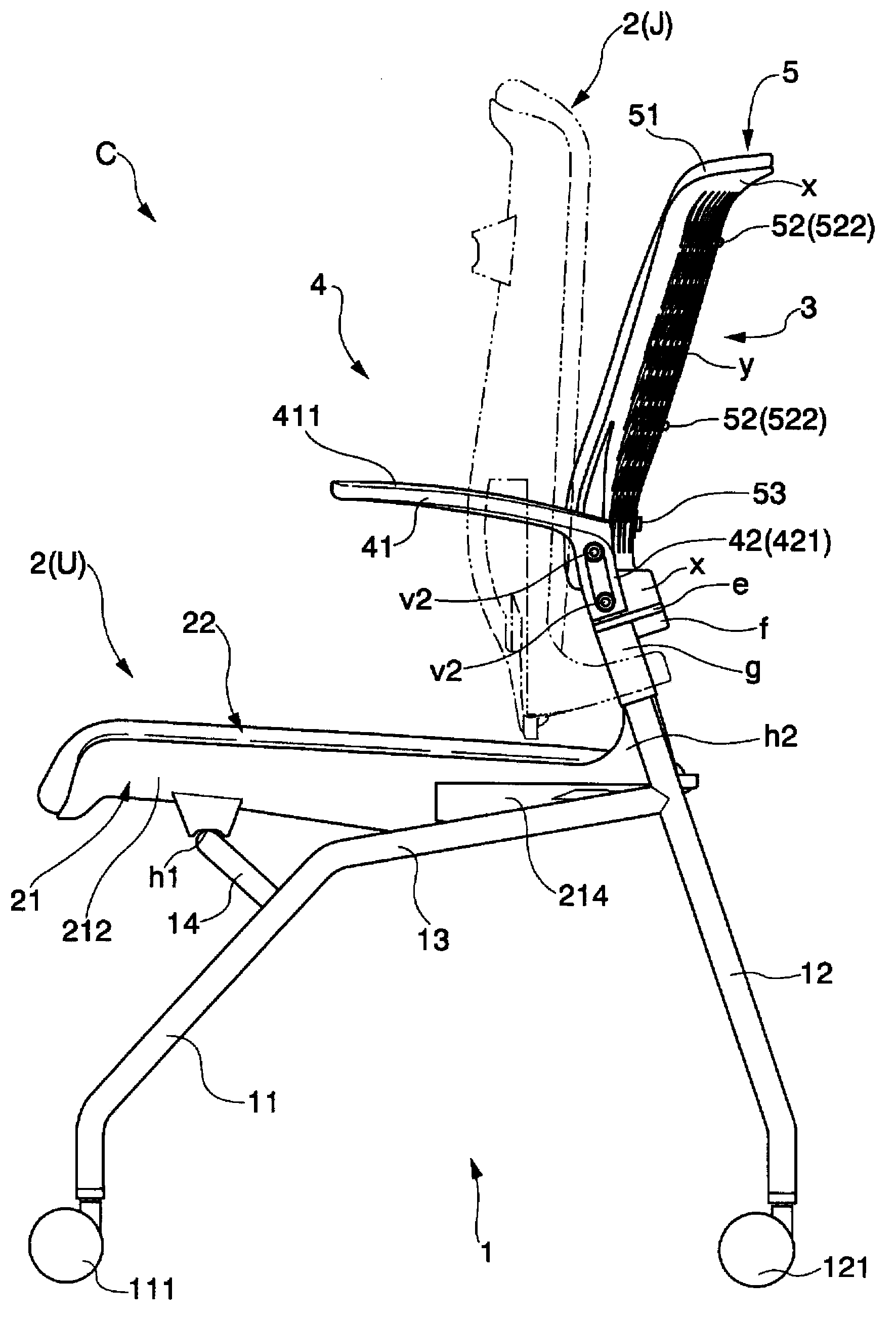
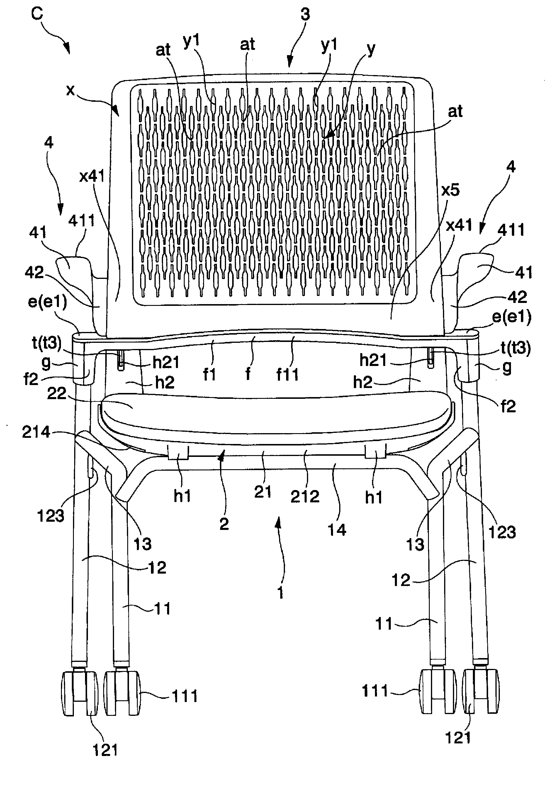
[0034] This embodiment is an embodiment in which the present invention is applied to a chair C that can be nested in the front-rear direction, that is, a chair C that can be stacked in the horizontal direction. like figure 2 As shown, the chair C is configured such that the seat 2 can rotate between the use position (U) and the pop-up position (J), and when the seat 2 is kept at the pop-up position (J), it can rotate in the front-rear direction. Nests with other chairs formed into the same structure.

[0035] The chair C is formed by supporting a seat 2 , a backrest 3 , and an armrest 4 with respect to a supporting body 1 , and an optional back cushion 5 is detachably attached to the backrest 3 . Furthermore, the chair C is provided with a horizontal frame 15 erected between the upper ends of the left and right rear legs 12, a backrest 3 supported by the horizontal frame 15, an...


PUM


Abstract

The invention provides a chair, which has a backrest which is composed of a plurality of holes and made from resin, and which is capable of increasing elastic deformation. The chair (C) comprises a backrest (3) which comprises a plurality of long holes (y1) and is made from resin. The long hole (y1) comprises a wide-width part (y11) of an equal-width part (y111) which extends along the length direction, and a narrow-width part (y12) which is connected to the wide-width part (y11) and is formed in a manner of equal width and extends along the length direction.

Description

technical field [0001] The present invention relates to a chair suitable for school use, office use, and the like. Background technique [0002] Conventionally, among such chairs, a chair provided with a resin backrest formed with a plurality of holes is known (for example, refer to Patent Document 1). [0003] However, almost all conventional backrests have holes formed in substantially equal-width rectangular shapes or simply circular hole shapes, and the degree of freedom in design for imparting elastic deformation is low. [0004] Patent Document 1: Japanese Patent Laid-Open No. 2002-125790 Contents of the invention [0005] The present invention has been made in view of the above situation, and an object of the present invention is to provide a chair in which a degree of freedom in design for imparting elastic deformation can be increased in a resin backrest formed with a plurality of holes. [0006] That is, the chair of the present invention is configured as follo...

Claims


Application Information

Patent Timeline
IPC IPC(8): A47C3/00A47C7/40
Inventor 铃木正义
Owner KOKUYO CO LTD
Why Eureka
Try Eureka