
Wheel hub automatic water soaking device

A wheel hub, automatic technology, applied in the field of foundry equipment, can solve the problems of high labor intensity of foundry workers, low production efficiency of wheel hubs, and potential safety hazards, saving time and effort in handling, simple and convenient cooling process by soaking in water, and avoiding potential safety hazards. Effect

Active Publication Date: 2014-04-23
ZHEJIANG JINFEI KAIDA WHEEL
View PDF6 Cites 16 Cited by
  • Summary
  • Abstract
  • Description
  • Claims
  • Application Information

AI Technical Summary

Problems solved by technology

[0002] In the existing casting equipment, after the hub casting is separated from the mold, it falls on a pallet that can swing around a point. The casting worker first rotates the pallet to make the hub casting leave the upper and lower mold clamping areas of the casting equipment, and then clamps the hub casting with pliers. Remove it from the pallet and place it in the water tank to soak in water to cool. After the wheel hub casting is cooled, the casting worker uses the pliers to clamp the wheel hub casting again and removes it from the water tank and places it on the subsequent workbench. In this way, the wheel hub casting The process of soaking in water is completely carried out manually, and the casting workers need to be in close contact with the high-temperature wheel hub castings during the transportation of the hub castings, which poses safety hazards. low efficiency

Method used


Image

  • Wheel hub automatic water soaking device
  • Wheel hub automatic water soaking device
  • Wheel hub automatic water soaking device

Examples


Embodiment Construction

[0039] In order to understand the above-mentioned purpose, features and advantages of the present invention more clearly, the present invention will be further described in detail below in conjunction with the accompanying drawings and specific embodiments. It should be noted that, in the case of no conflict, the embodiments of the present application and the features in the embodiments can be combined with each other.

[0040] In the following description, many specific details are set forth in order to fully understand the present invention. However, the present invention can also be implemented in other ways than described here. Therefore, the protection scope of the present invention is not limited by the specific implementation disclosed below. Example limitations.

[0041] Refer to the attached figure 1 to attach Figure 9 The automatic hub water soaking device provided according to some embodiments of the present invention is described.

[0042] Such as figure 1 , ...


PUM


Abstract

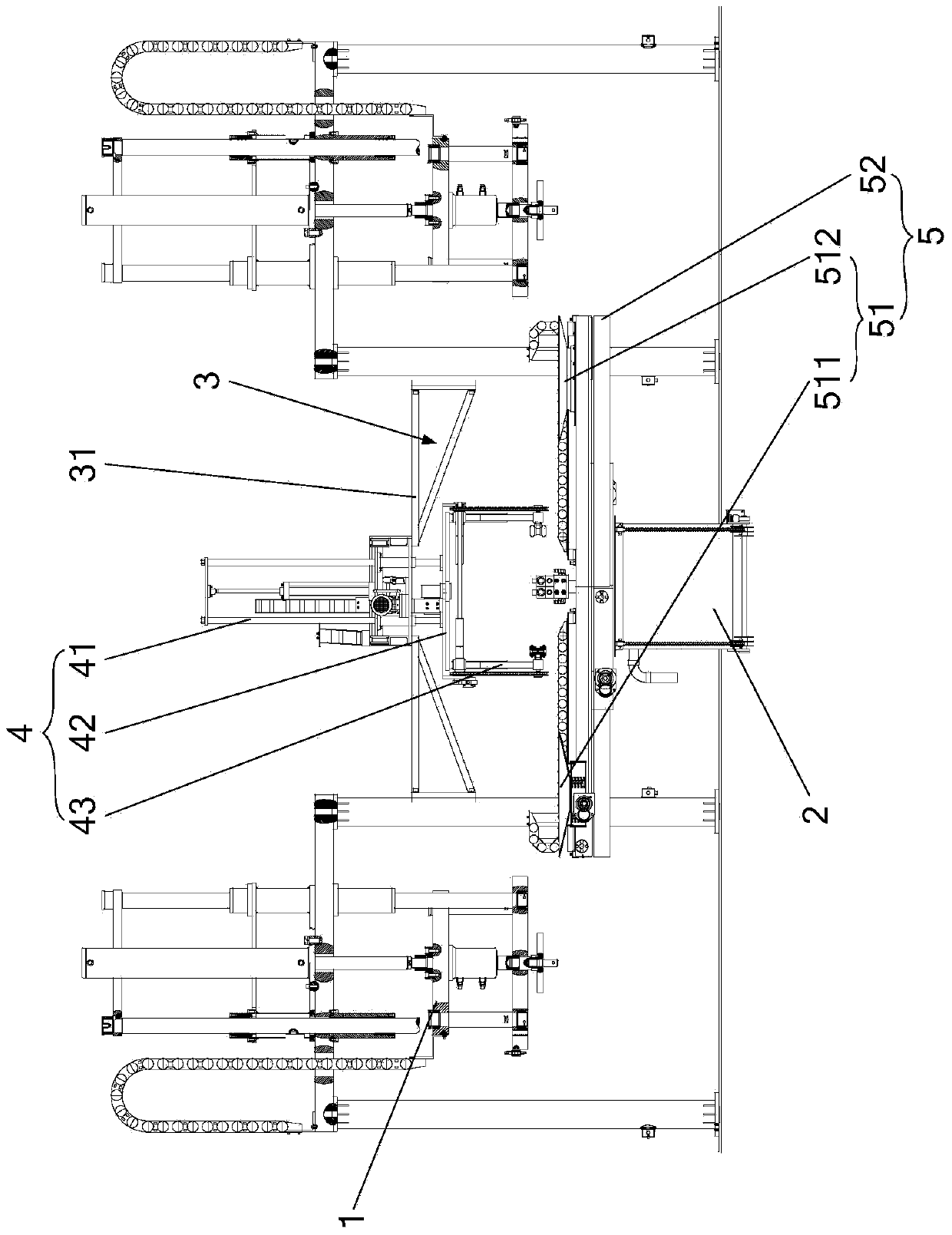
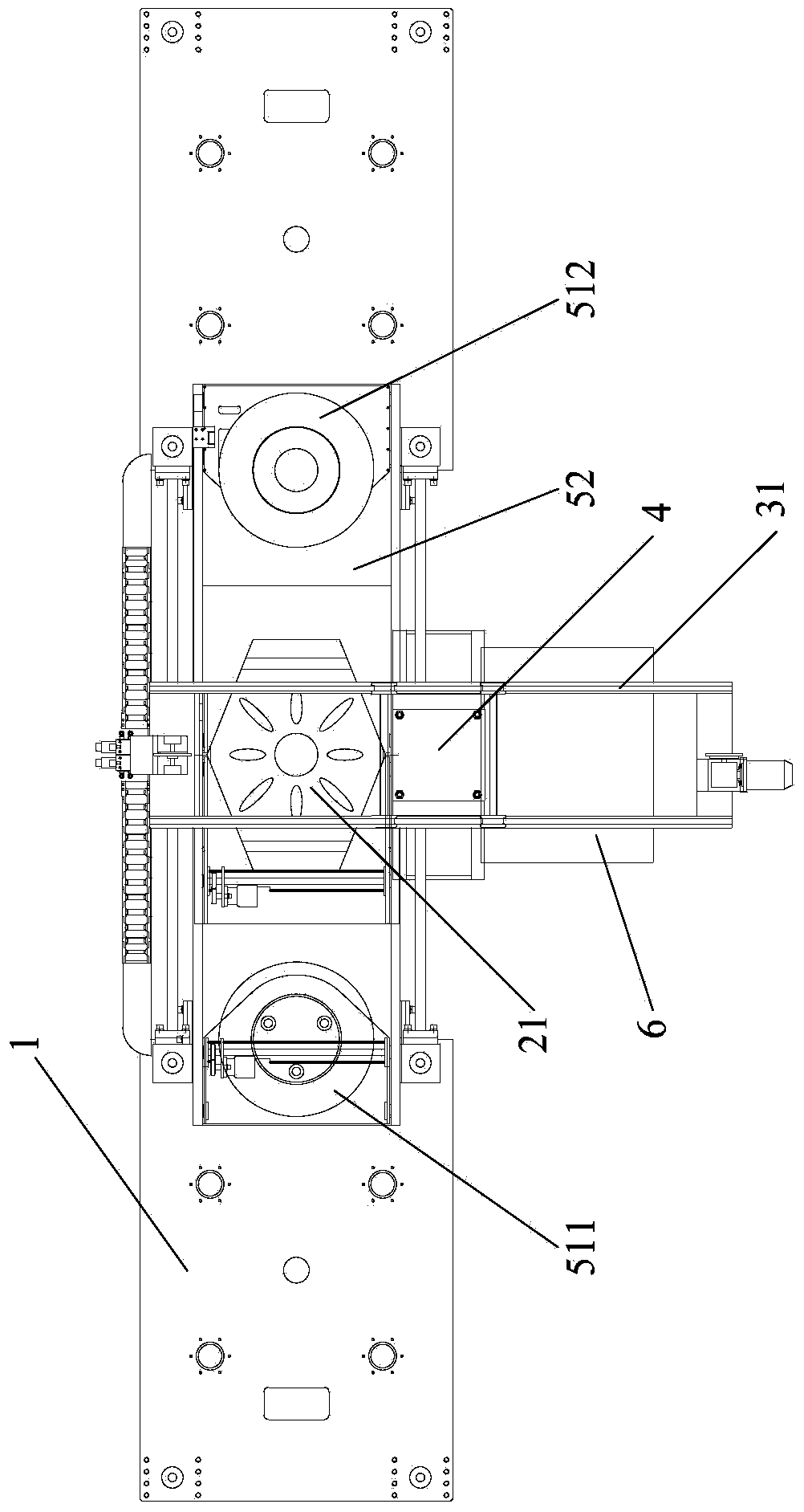
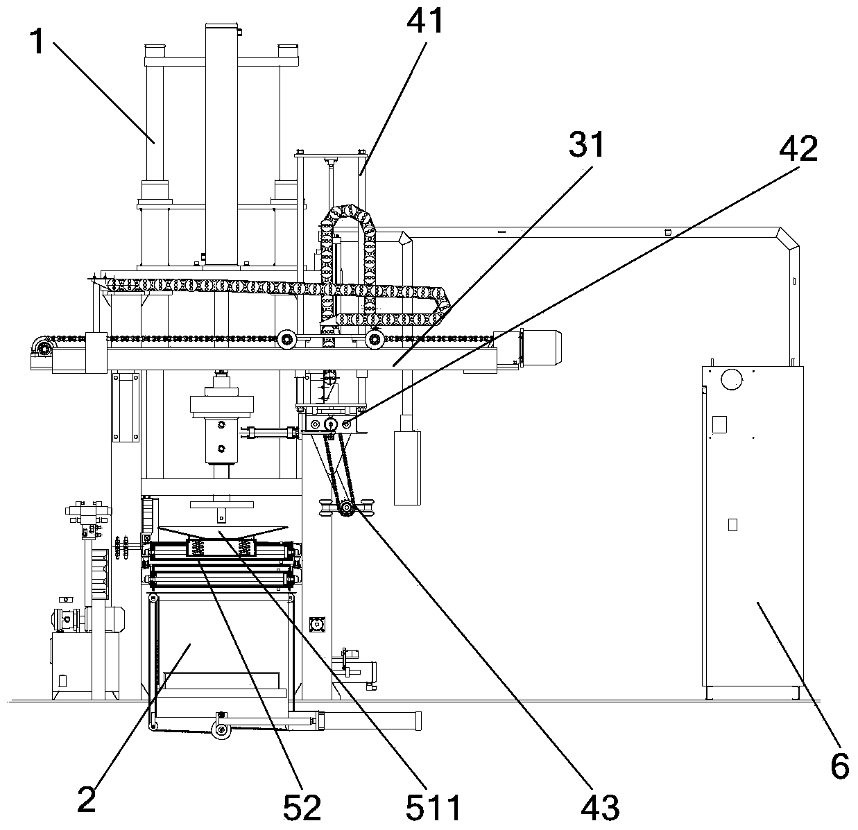
The invention provides a wheel hub automatic water soaking device. The wheel hub automatic water soaking device comprises a water soaking tank, a gantry frame, a mechanical arm and a material collecting mechanism; a water soaking platform which is arranged inside the water soaking tank can move vertically; the gantry frame is arranged above the water soaking tank; the mechanism arm which is installed on the gantry frame in a movable mode is arranged above the water soaking tank; the material collecting mechanism which is arranged between two wheel hub casting machines is located between the mechanical arm and the water soaking tank; the material collecting mechanism can convey die released castings of the wheel hub casting machines to above the water soaking tank; the mechanical arm grabs and places the castings on the water soaking platform after the castings are turned over; the water soaking platform moves downward to perform water soaking and cooling on the castings; the water soaking platform moves upward after the castings are cooled; the mechanical arm grabs and turns over the castings to drain water and then conveys the castings to a follow-up work bench after rotation. The wheel hub automatic water soaking device has the advantages of being simple in structure, saving time and force due to the fact that the castings are conveyed through the material collecting mechanism and the mechanical arm, effectively solving potential risks and improving the production efficiency of wheel hubs.

Description

technical field [0001] The invention relates to the field of casting equipment, and more specifically, to an automatic water soaking device for a wheel hub. Background technique [0002] In the existing casting equipment, after the hub casting is separated from the mold, it falls on a pallet that can swing around a point. The casting worker first rotates the pallet to make the hub casting leave the upper and lower mold clamping areas of the casting equipment, and then clamps the hub casting with pliers. Remove it from the pallet and place it in the water tank to soak in water to cool. After the wheel hub casting is cooled, the casting worker uses the pliers to clamp the wheel hub casting again and removes it from the water tank and places it on the subsequent workbench. In this way, the wheel hub casting The process of soaking in water is completely carried out manually, and the casting workers need to be in close contact with the high-temperature wheel hub castings during t...

Claims


Application Information

Patent Timeline
Patent Type & Authority Applications(China)
IPC IPC(8): B22D30/00
Inventor 葛炳灶傅成葛础
Owner ZHEJIANG JINFEI KAIDA WHEEL
Learn More