
transmitter

A transmitter and phase-locked loop technology, applied in the field of transmitters, can solve problems such as excessive noise, and achieve the effect of preventing traction problems and eliminating the relationship of whole harmonics.

Active Publication Date: 2015-09-09
AMPLEON NETHERLANDS
View PDF4 Cites 0 Cited by
  • Summary
  • Abstract
  • Description
  • Claims
  • Application Information

AI Technical Summary

Problems solved by technology

However, this introduces excess noise as many devices are inserted in the feedforward path, each adding their own contribution to the phase noise

Method used


Image

  • transmitter
  • transmitter
  • transmitter

Examples


Embodiment Construction

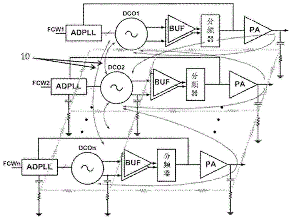
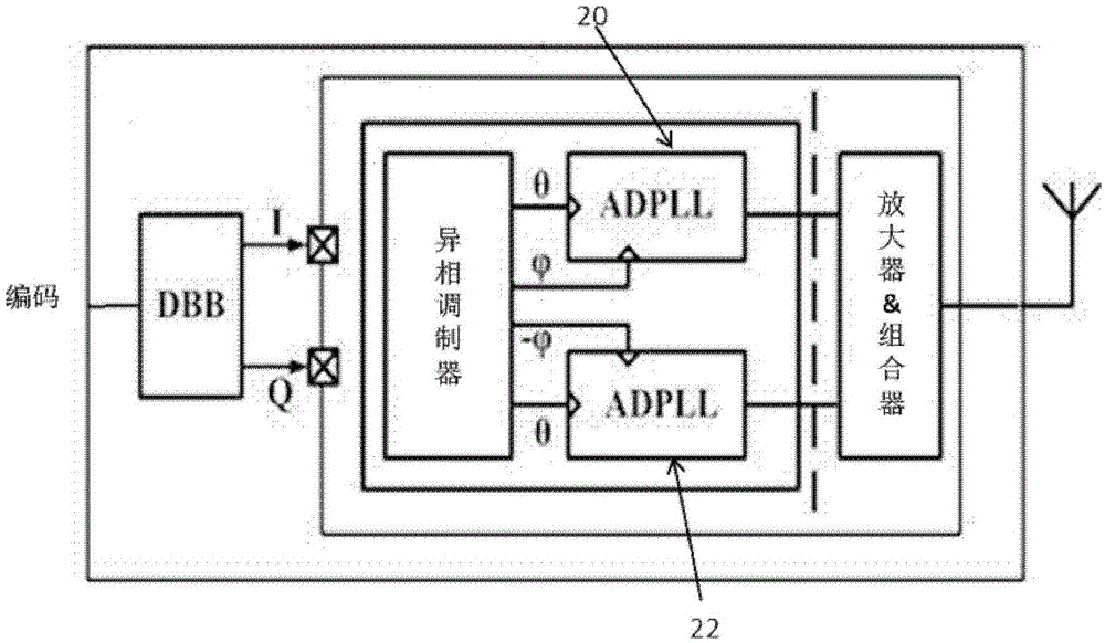
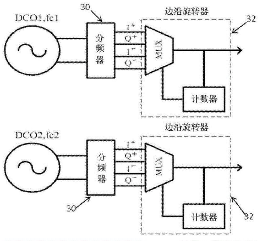
[0046] The present invention provides a transmitter comprising two phase locked loops (PLL) for controlling respective oscillators and performing different phase / frequency modulations, the two phase locked loops are preferably all digital PLLs, the oscillators are preferably Digitally Controlled Oscillator (DCO). A plurality of phases, preferably equidistant phases, originate from respective oscillators and a multiplexer forms the output signal from the combination of the phases. The oscillators can operate at different frequencies, neither of the two being an integer multiple of the other, nor the output, so the average frequency of the output signals of the multiplexers of the first and second PLLs can be are substantially the same. It is a matter of reducing pull with a circuit implemented at low power and small area and with digitally enhanced versatility.

[0047]By properly arranging the power amplifier network, the present invention can thus provide a new out-of-phase...


PUM


Abstract

The invention provides a transmitter comprising two (or more) phase locked loops controlling respective oscillators, and implementing different phase modulation. Multiple phases are derived from the respective oscillators, and an edge rotator forms an output signal from a combination of the phases. The oscillators can operate at different frequencies, neither of which is an integer multiple of the other, whereas the output signals of the multiplexers of the first and second phase locked loops are closer in frequency and can be the same. This reduces the problem of pulling, with a circuit that can be implemented with low power and area and with the versatility of being digitally intensive.

Description

technical field [0001] The invention relates to transmitters, in particular to transmitters combining two channels with different phase modulations. This type of transmitter is called an out-of-phase transmitter. Background technique [0002] There is an increasing demand for highly reconfigurable modulators that can handle different wireless communication standards, such as 3GPP's GSM, WCDMA, and LTE. [0003] The continuous advance of system-level integration and, more recently, the integration of multiple radios / channels on the same system-on-chip (SoC) die presents particular difficulties. Examples of such integration apply to multiple radio frequency cores or communication channels. In these RF-SoC designs, interference coupling greatly limits the performance of the RF circuits. One of the main problems with this coupling is injection pulling. Injection pulling and signal integrity issues continue to grow. [0004] Any oscillatory system, such as a phase-locked loo...

Claims


Application Information

Patent Timeline
Patent Type & Authority Patents(China)
IPC IPC(8): H04B1/04H03L7/099
CPCH04B2001/0491H04J1/20H04B1/0483
Inventor 赛义德·阿米尔·瑞扎·阿罕默德·米尔罗伯特·波格但·斯塔泽维斯基马克·皮特·范德海登
Owner AMPLEON NETHERLANDS
Learn More