
Touch display structure

A touch display and touch module technology, which is applied to instruments, electrical digital data processing, and input/output processes of data processing, etc., can solve problems such as easy mechanical interference and fragile surface glass, and achieve interference problems. reduced effect

Inactive Publication Date: 2014-04-09
AU OPTRONICS CORP
View PDF0 Cites 2 Cited by
  • Summary
  • Abstract
  • Description
  • Claims
  • Application Information

AI Technical Summary

Problems solved by technology

[0006] 3. When the double-sided adhesive 95 is poorly designed, it is easy to interfere with the mechanism
[0007] 4. When the surface glass of the touch module 92 is combined with the system frame 94, there is no buffer in the middle, so the surface glass of the touch module 92 is easily broken when a collision occurs

Method used


Image

  • Touch display structure
  • Touch display structure
  • Touch display structure

Examples


Embodiment Construction

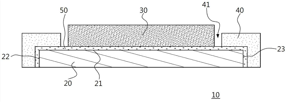
[0056] Please also see image 3 as shown, image 3 It is a schematic diagram of an embodiment of the touch display structure of the present invention, as shown in the figure: the touch display structure 10 in this embodiment at least includes a touch module 20, a display module 30 and a frame 40, wherein the touch module 20 has The joint surface 21 and at least two side surfaces 22, 23, and the two side surfaces 22, 23 are respectively adjacent to the joint surface 21 opposite to the left and right. In addition, the joint surface 21 and the two side surfaces 22, 23 of the touch module 20 are covered with One layer of adhesive layer 50 is a transparent and fluid adhesive substance.

[0057] The above-mentioned frame 40 is arranged on the periphery of the touch module 20 and bonded with the adhesive layer 50. In other words, the adhesive layer 50 is filled between the frame 40 and the touch module 20, and the touch module 20 is arranged on the frame 40 and the frame 40 has an ...


PUM


Abstract

The invention provides a touch display structure and a manufacturing method thereof. The touch display structure at least comprises a touch module, a display module and a frame, and an adhesion layer is coated on the touch module completely. In the manufacturing method, coating of the adhesion layer is performed when an adhesive material still has fluidity, so that the adhesion layer can be coated on the surface and side faces of the touch module averagely; when the frame is arranged on the periphery of the touch module and fitted with the adhesion layer, part of the adhesion layer can fit with the frame; the adhesion layer is formed between each of two side faces of the touch module and the frame, so that gaps between the touch module and the frame are filled by the adhesion layer, and buffering effect can be provided to reduce breaking of glass of the touch module from the edge due to collision.

Description

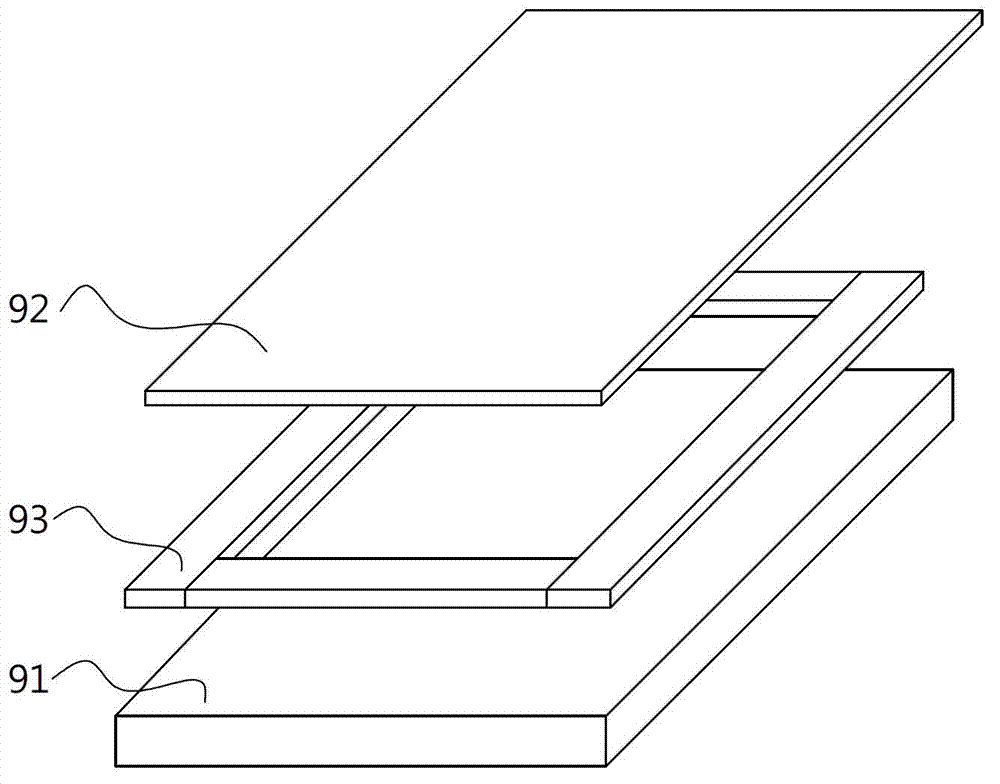
technical field [0001] The invention relates to a touch display structure and a manufacturing method of the touch display structure. Background technique [0002] The current bonding technology of touch panel module and display module can be divided into two bonding methods: direct bonding and air bonding. To reduce costs, mostly Air Bonding is still the main method, please refer to figure 1 , Air Bonding is to send the finished panel 91 and the touch module 92 to the assembly plant, and use the air-shaped adhesive tape 93 to carry out the bonding action, but the panel factory now intends to invest in direct bonding (Direct Bonding) equipment, And improve the bonding process, move the backlight module manufacturing process backwards, and let the panel factory take the lead in bonding the touch module and the Cell first. In addition to improving the yield and efficiency, it also increases the quality of medium and large size cut-in touch controls. [0003] However, direct b...

Claims


Application Information

Patent Timeline
IPC IPC(8): G06F3/041
Inventor 黄宗彦余宣纬李达汉梅光华
Owner AU OPTRONICS CORP
Learn More