Tricycle curved beam frame

A tricycle and curved beam technology, which is applied in the field of tricycle curved beam frame, can solve the problems of inability to guarantee the strength of the frame, unfavorable heat dissipation of the engine, large driving vibration, etc., achieve good ventilation effect, obvious synergistic force bearing effect, and improve bearing capacity Effect

Active Publication Date: 2016-04-13
HENAN LONGXIN LOCOMOTIVE
View PDF7 Cites 1 Cited by
  • Summary
  • Abstract
  • Description
  • Claims
  • Application Information

AI Technical Summary

Problems solved by technology

Existing tricycle curved beam vehicle frame generally comprises head pipe, front left beam, front right beam, main beam, rear left beam and rear right beam, head tube, front left beam, front right beam, main beam, rear left beam and The rear and right beams are fixedly connected to each other to form an integral frame; since the existing tricycle curved beam frame bears corresponding loads during use and needs to have a lighter structure, it is necessary to optimize the structure of the tricycle curved beam frame , in order to achieve lightness, high strength, and easy arrangement of other equipment on the vehicle; while the frame in the prior art is due to comprehensive consideration of strength and equipment arrangement, the engine installation position is located under the seat, which is not conducive to engine heat dissipation after the vehicle is installed. At the same time, the overall structural layout of the vehicle frame composed of the above-mentioned beams cannot guarantee the strength of the vehicle frame, and it is prone to overall deformation or relatively large driving vibration.

Method used


Image

  • Tricycle curved beam frame
  • Tricycle curved beam frame
  • Tricycle curved beam frame

Examples


Embodiment Construction

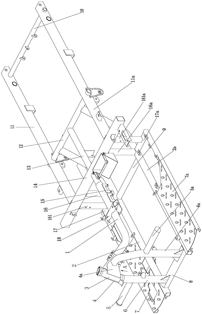
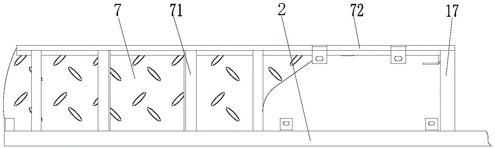
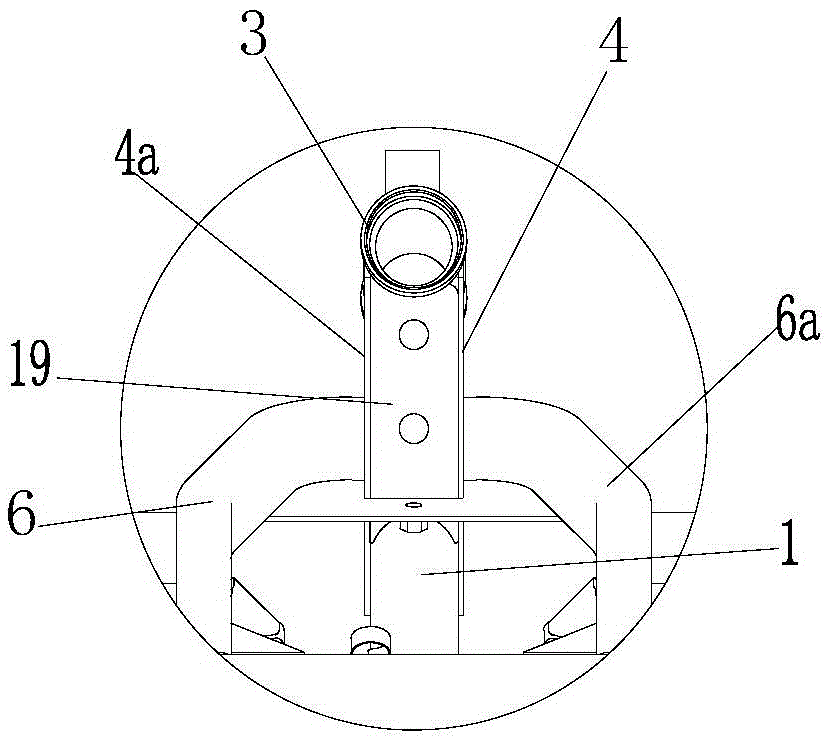
[0020] figure 1 It is a structural schematic diagram of the present invention, figure 2 It is a schematic diagram of the structure of the pedal assembly, image 3 for figure 1 Partial view along A, as shown in the figure: the tricycle curved beam frame of the present embodiment includes a head pipe 3, a front frame, a main beam 14 and a rear frame that are fixedly connected to each other to form a frame, and the front frame It is integrated with the rear frame through the main beam 14. The front frame includes the left front side beam 2a, the right front side beam 2 and the main beam 1 whose front end is fixedly connected to the head pipe 3 and the rear end is fixedly connected to the main beam 14. The main beam 1 is a curved beam structure with a downward bend; the use of the curved beam structure is beneficial to the arrangement of other equipment. In the present invention, the fixed connection and fixed arrangement generally adopt welding. Of course, the method of assemb...


PUM


Abstract

The invention discloses a tricycle camber-beam frame. The tricycle camber-beam frame comprises a heading tube, a front frame, a main transverse beam and a rear frame, which are in fixed connection to form the tricycle camber-beam frame. The front frame is connected with the rear frame by the main transverse beam to form an integral part. The front frame comprises a left front edge beam, a right front edge beam and a main beam. The front end of the main beam is fixedly connected with the heading tube and the rear end of the main beam is connected with the main transverse beam. The main beam is in a structure of downward camber beam. The main beam and the main transverse beam are used as main load-bearing parts, so that the structure of camber-beam is formed with the integration with the structures of edge beam and transverse beam. Accordingly, the force condition of the tricycle camber-beam frame is improved, rational distribution of the load-bearing parts of the tricycle camber-beam frame and all the beams and tubes are capable of bearing the force collaboratively without adding weights to the tricycle camber-beam frame or the tricycle. The overall strength of the tricycle camber-beam frame can be improved so as to guarantee the stability and safety of the tricycle and the positions of devices as engines and the like are changed so as to improve the cooling effect and ensure the engine in smooth operation.

Description

technical field [0001] The invention relates to a tricycle component, in particular to a tricycle curved beam frame. Background technique [0002] The frame is the main load-bearing part of the vehicle, and its strength and fatigue life are very important to the vehicle. Especially for tricycles and other small light vehicles that need to bear a certain load, it is necessary to comprehensively consider the lightness and strength of the vehicle frame. Existing tricycle curved beam vehicle frame generally comprises head tube, front left beam, front right beam, main beam, rear left beam and rear right beam, head tube, front left beam, front right beam, main beam, rear left beam and The rear and right beams are fixedly connected to each other to form an integral frame; since the existing tricycle curved beam frame bears corresponding loads during use and needs to have a lighter structure, it is necessary to optimize the structure of the tricycle curved beam frame , in order to...

Claims


Application Information

Patent Timeline
Patent Type & Authority Patents(China)
IPC IPC(8): B62K5/06
Inventor 冯勇冯仁川
Owner HENAN LONGXIN LOCOMOTIVE
Why Eureka
Try Eureka