A lock body for a side hinged door
A technology of door locks and lock casings, applied in the field of door and window hardware, which can solve problems such as high manufacturing costs, low yield, and complex lock body structures, and achieve the effects of simplified transmission methods, reduced parts and components, and reduced manufacturing costs
- Summary
- Abstract
- Description
- Claims
- Application Information
AI Technical Summary
Problems solved by technology
Method used
Image

Examples
Embodiment 1
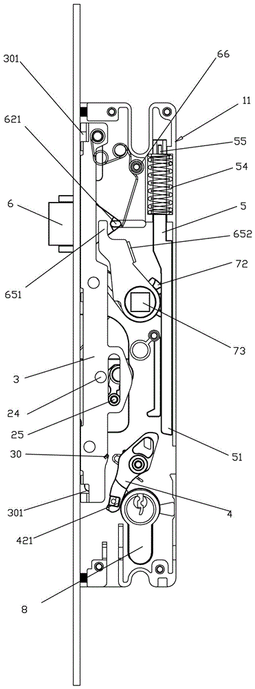
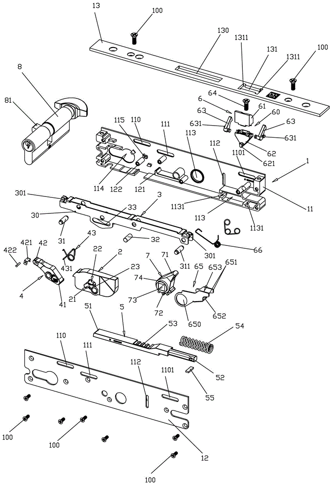
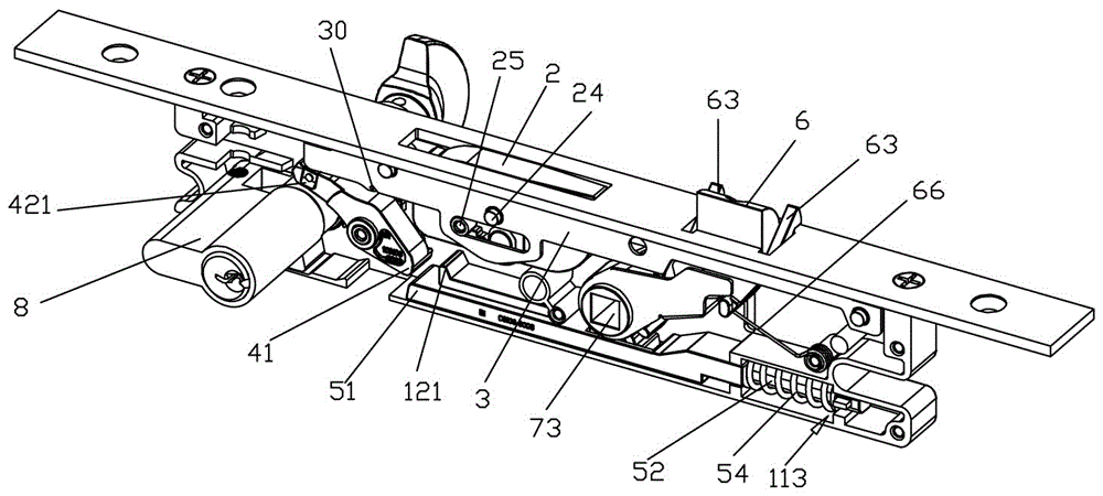
[0036] see Figure 1-6 , the present invention provides a lock body for a side hinged door, comprising a lock housing 1, a locking member 2, a transmission member 3, a bridge member 4, a first pusher 7, a second pusher 5, a bridge reset member 43 and a toggle member 8; wherein, the lock case 1 includes a lower case 11, an upper case 12 and a side case 13, and the lower case 11, the upper case 12 and the side case 13 are connected by several screws 100 to form a cavity for accommodating other parts .
[0037] see Figure 1-6 , the two ends of the lock housing 1 are provided with a first transmission hole 110 and a second transmission hole 1101 , and a waist-shaped hole 111 is provided in the middle. Wherein, the first transmission hole 110 and the second transmission hole 1101 are both waist-shaped holes, and the transmission member 3 is installed in the first transmission hole 110 and the second transmission hole through the first installation shaft 31 and the second install...
Embodiment 2
[0056] see Figure 1-10 , this embodiment adds a bolt unit 6 on the basis of Embodiment 1, and the bolt unit 6 is installed in the lock housing 1. The bolt unit 6 includes a bolt body 60, a bolt moving piece 65, a bolt Reset spring 66; the oblique tongue shifting piece 65 includes an oblique tongue actuating piece installation hole 650, an oblique tongue pushing end 651, an oblique tongue actuating piece stop end 652 and an oblique tongue actuating member installation groove 653, the oblique tongue actuating piece installation groove 653, The tongue shifting piece installation hole 650 is provided at the lower end of the oblique tongue shifting piece 65. The oblique tongue moving piece installation hole 650 is a round hole. Located on the left and right sides of the upper end of the oblique tongue driving piece 65 , the installation groove 653 of the oblique tongue driving piece is opened in the middle of the oblique tongue driving piece 65 .
[0057] The first pusher 7 is lo...
Embodiment 3
[0070] see Figure 12-16 In this embodiment, on the basis of Embodiment 1 or Embodiment 2, a transmission member locking unit is added, and the transmission member locking unit includes a locking hole 91 and a locking reset member 93, and the locking hole 91 is horizontally opened in On the transmission part 2, it is a waist-shaped hole, and the pushing part 31 of the second transmission part is installed in the locking hole 91; in this embodiment, a corner is provided under the first transmission hole 110, and the whole It is L-shaped, the two ends of the second transmission part pushing part 31 are installed in the first transmission hole 110 , and the locking reset part 93 is installed on one side of the second transmission part pushing part 31 .
[0071] After adopting the above technical solution, when the transmission part 3 moves downward to drive the locking part 2 to be in the locked state, the pushing part 31 of the second transmission part is located below the first...
PUM
 Abstract
Description
Claims
Application Information
 - R&D
- Intellectual Property
- Life Sciences
- Materials
- Tech Scout
- Unparalleled Data Quality
- Higher Quality Content
- 60% Fewer Hallucinations
Browse by: Latest US Patents, China's latest patents, Technical Efficacy Thesaurus, Application Domain, Technology Topic, Popular Technical Reports.
© 2025 PatSnap. All rights reserved.Legal|Privacy policy|Modern Slavery Act Transparency Statement|Sitemap|About US| Contact US: help@patsnap.com