
Method and equipment for determining positional information of calculation equipment in complete machine cabinet

A technology for calculating equipment and equipment location, applied in the server field, can solve problems such as location information positioning efficiency affecting servers, and achieve the effect of solving asset positioning problems, improving management experience, and improving accuracy and efficiency

Active Publication Date: 2014-03-26
BEIJING BAIDU NETCOM SCI & TECH CO LTD
View PDF6 Cites 25 Cited by
  • Summary
  • Abstract
  • Description
  • Claims
  • Application Information

AI Technical Summary

Problems solved by technology

However, the existing server asset management technology usually allocates the rack position before the server enters the computer room, so as to ensure that the server can obtain unique location information after the server enters the computer room, but for the whole cabinet as a whole When delivering products, the rack positions cannot be allocated in advance. The existing technology cannot quickly and accurately locate the servers in the entire cabinet and realize the asset management of the entire cabinet. In particular, when a server fails, it affects the Positioning efficiency of server location information

Method used


Image

  • Method and equipment for determining positional information of calculation equipment in complete machine cabinet
  • Method and equipment for determining positional information of calculation equipment in complete machine cabinet
  • Method and equipment for determining positional information of calculation equipment in complete machine cabinet

Examples


Embodiment Construction

[0025] The present invention will be described in further detail below in conjunction with the accompanying drawings.

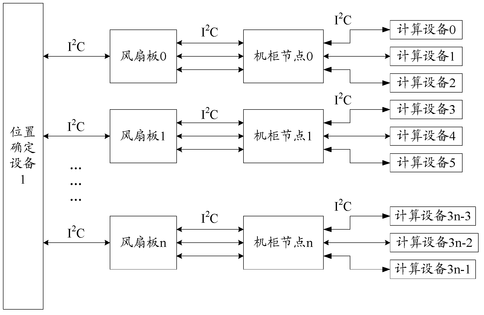
[0026] figure 1 A rack system diagram for determining location information of a computing device in the rack according to one aspect of the present invention is shown. Wherein, the location determination device 1 passes the address bus such as I 2 The C bus is connected to multiple fan boards such as fan board 0 to fan board n, and the fan boards pass through the cabinet nodes via the address bus such as I 2 The C bus is connected to the computing device, and finally, the location determination device 1 is connected to each computing device in the whole cabinet, so as to realize the query of the location information of each computing device in the whole cabinet through the address bus. here, figure 1 The numbers corresponding to the fan boards, cabinet nodes, or computing devices in , only indicate the serial numbers of the corresponding devices, not the r...


PUM


Abstract

The invention aims to provide a method and equipment for determining positional information of calculation equipment in a complete machine cabinet. Specifically, position determination equipment establishes or updates a first relationship of bus address information and node identification information corresponding to the bus address information of machine cabinet node in the complete machine cabinet; an equipment position request about target calculation equipment is sent through an address bus; an equipment identification response corresponding to the equipment position request is received through the address bus; the target equipment positional information of the target calculation equipment is determined according to the target node identification information and the positional information of the complete machine cabinet. Compared with the prior art, according to the target node identification information contained in the equipment identification response corresponding to the equipment position request received by the address bus and the positional information of the complete machine cabinet, the target equipment positional information of the target calculation equipment is determined, so that the effect of quickly and accurately positioning a server in the complete machine cabinet is achieved, and the problem of asset positioning of the complete machine cabinet is solved.

Description

technical field [0001] The invention relates to the technical field of servers, in particular to a technology for determining position information of computing equipment in a complete cabinet. Background technique [0002] The rapid development of the Internet is inseparable from servers with high-speed computing capabilities, long-term reliable operation, and powerful external data throughput capabilities. However, the existing server asset management technology usually allocates the rack position before the server enters the computer room, so as to ensure that the server can obtain unique location information after the server enters the computer room, but for the whole cabinet as a whole When delivering products, the rack positions cannot be allocated in advance. The existing technology cannot quickly and accurately locate the servers in the entire cabinet and realize the asset management of the entire cabinet. In particular, when a server fails, it affects the The positi...

Claims


Application Information

Patent Timeline
IPC IPC(8): H04L29/08
Inventor 刘洪梅陈国峰张家军
Owner BEIJING BAIDU NETCOM SCI & TECH CO LTD
Learn More