Optical path protecting instrument with band switching function and control method of optical path protecting instrument

A technology of band conversion and band conversion, which is applied in the field of optical path protectors, can solve problems such as limitations, and achieve the effect of ensuring normal use

Inactive Publication Date: 2014-03-26
STATE GRID ANHUI ELECTRIC POWER +1
View PDF6 Cites 0 Cited by
  • Summary
  • Abstract
  • Description
  • Claims
  • Application Information

AI Technical Summary

Problems solved by technology

[0002] At present, only a few foreign companies have the ability to research and produce optical fiber protection equipment, mainly JDS, E-TEK, Dicon, etc., but none of them have the automatic detection function for the optical band, so they will be limited by the band of the optical module

Method used


Image

  • Optical path protecting instrument with band switching function and control method of optical path protecting instrument

Examples


Embodiment Construction

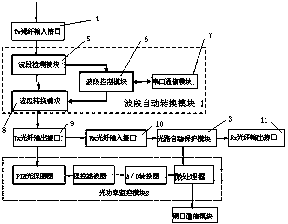
[0014] see figure 1 , An optical path protection instrument, including an optical power monitoring module 2 and an optical path automatic protection module 3, the optical power monitoring module 2 and the optical path automatic protection module 3 are interactively connected, and also includes a band automatic conversion module 1, and the band automatic conversion module 1 includes The band detection module 5, the band conversion module 8, the band control module 6, and the serial communication module 7; the input end of the band detection module 5 is connected to the Tx optical fiber input interface 4 for transmitting and receiving optical signals, and the output of the band detection module 5 Terminals are respectively connected with the signal input terminals of the band control module 6 and the band conversion module 8, the signal output terminal of the band control module 6 is connected with the signal input terminal of the band conversion module 8, and the band control mod...


PUM


Abstract

The invention relates to an optical path protecting instrument with a band switching function and a control method of the optical path protecting instrument. The optical path protecting instrument comprises an optical power monitoring module, an optical path automatic protecting module, a band automatic switching module, a band automatic switching module signal input end and a Tx optical fiber input interface, wherein the optical power monitoring module is interactively connected with the optical path protecting module, and the Tx optical fiber input interface is used for transmitting and receiving optical signals. A band automatic switching module signal output end is connected with the band automatic switching module signal input end through a Tx optical fiber output interface and an Rx optical fiber input interface. The band automatic switching module signal output end is connected with the signal input end of the optical power monitoring module through the Tx optical fiber output interface. By the optical path protecting instrument and the protecting method thereof, automatic detection and conversion can be performed on optical bands firstly, and the optical module bands of the optical bands are enabled to be unlimited.

Description

Technical field [0001] The invention relates to the field of optical fiber protection equipment, in particular to an optical path protection instrument. Background technique [0002] At present, only a few foreign companies have the ability to research and produce optical fiber protection equipment, mainly JDS, E-TEK, Dicon, etc., but none of them have the automatic detection function for the optical band, so they will be limited by the optical module band. With the rapid development of optical communication technology, especially the development of all-optical communication network technology, the demand for optical fiber protection equipment (including domestic demand) will increase rapidly. The development of optical fiber protection equipment with automatic detection and conversion of optical bands is of special significance for reducing the cost of network node construction and upgrading, improving the reliability of network operation and the ability to resist destruction. ...

Claims


Application Information

Patent Timeline
Patent Type & Authority Applications(China)
IPC IPC(8): H04B10/032H04B10/07
Inventor 卓文合张引强黄影叶志远李志浩陈是同
Owner STATE GRID ANHUI ELECTRIC POWER
Why Eureka
Try Eureka