Switching power supply device

A technology of switching power supply and switching elements, which is applied in the direction of output power conversion devices, electrical components, and adjustment of electrical variables, etc.

Active Publication Date: 2014-03-26
SANKEN ELECTRIC CO LTD
View PDF4 Cites 9 Cited by
  • Summary
  • Abstract
  • Description
  • Claims
  • Application Information

AI Technical Summary

Benefits of technology

The technical feature described this technology allows for efficient use of electricity while still maintaining good performance on high-voltage equipment such as electrical devices or batteries that require regulated voltages like alternating current (AC). This means it can be more energy-efficient than regular chargers due to its ability to release excessive charge quickly when needed again instead of constantly supplying full capacity with all remaining charges at once.

Problems solved by technology

The technical problem addressed in this patented technology relates to improving upon how quickly switches off electrical loads such as lights without generating excessive voltages at their ends. This can lead to misjudgment over users' experiences caused by these surges.

Method used


Image

  • Switching power supply device
  • Switching power supply device
  • Switching power supply device

Examples


Embodiment Construction

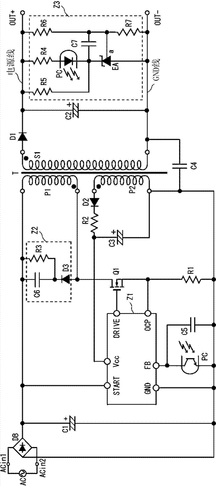
[0047] refer to figure 1 , The switching power supply device of this embodiment has a rectifier circuit DB, electrolytic capacitors C1, C2, C3, switching element Q1, transformer T, rectifier diodes D1, D2, resistors R1, R2, capacitors C4, C5, control circuit Z1, snubber circuit Z2, feedback circuit Z3.

[0048] The AC input terminals ACin1 and ACin2 of the rectifier circuit DB constituted by bridge diodes are connected to the AC power source AC, and the AC voltage input from the AC power source AC is full-wave rectified and output from the rectifier circuit DB. An electrolytic capacitor C1 is connected between the rectification output positive terminal and the rectification output negative terminal of the rectification circuit DB. In this way, a DC power supply in which the AC power supply AC is rectified and smoothed by the rectifier circuit DB and the electrolytic capacitor C1 can be obtained.

[0049] Between the positive terminal and the negative terminal of the electro...


PUM


Abstract

The invention provides a switching power supply device capable of ensuring the transient recovery of the voltage discharge of an electrolytic capacitor after the rectifying process, without the addition of power consumption. The switching power supply device comprises a rectifying circuit used for rectifying the AC voltage; an electrolytic capacitor used for rectifying and smoothing the AC voltage; a transformer used for applying a smoothed voltage onto the electrolytic capacitor; a switching element connected to the transformer (T); and a control circuit (Z1) used for enabling the switching on/off of the switching element. The control circuit (Z1) is composed of a start-up circuit (Z10) and a discharge circuit (Z14). The start-up circuit (Z10) is used for supplying the voltage of the electrolytic capacitor to the Vcc terminal of the control circuit (Z1). The discharge circuit (Z14) is connected with the Vcc terminal and is used for discharging the transient recovery voltage of the electrolytic capacitor.

Description


Claims


Application Information

Patent Timeline
Owner SANKEN ELECTRIC CO LTD
Why Eureka
Try Eureka