
Actuating drive

一种驱动装置、传动装置的技术,应用在机电装置、电动组件、机壳/外罩/支承物等方向,能够解决复杂等问题,达到价格便宜、高运行可靠性和调节精度、准确轴向定位的效果

Active Publication Date: 2014-03-26
海拉有限双合股份公司
View PDF6 Cites 2 Cited by
  • Summary
  • Abstract
  • Description
  • Claims
  • Application Information

AI Technical Summary

Problems solved by technology

It is known to the applicant to use sheet metal for radial positioning and fixing, and for axial positioning to use additional components such as corrugated washers or disc springs, so that radial and axial positioning is in the known servo Electric motors are generally more complex

Method used


Image

  • Actuating drive
  • Actuating drive
  • Actuating drive

Examples


Embodiment Construction

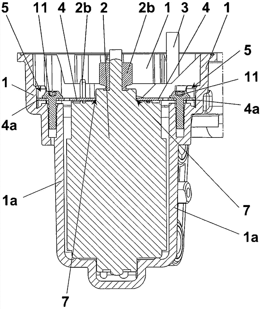
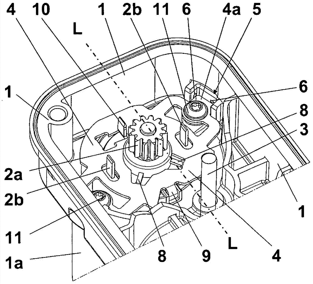
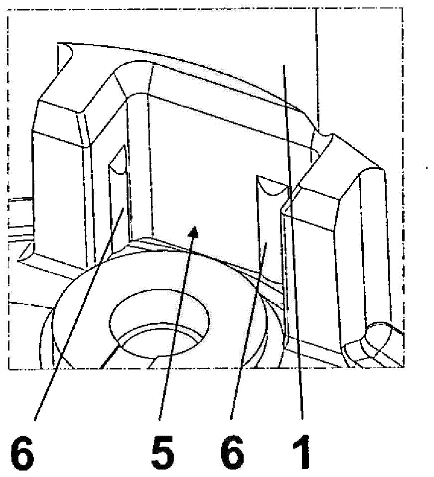
[0019] as from Figures 1 to 4 As can be seen in FIG. 1 , an adjusting drive comprises a housing 1 and (not shown) a cover and an output device, which is guided through the cover. The housing 1 and the cover are produced from plastic.

[0020] The housing 1 is substantially rectangular parallelepiped including a convex body 1a protruding from a bottom and having a pair of open sides disposed on the bottom. The convex body 1a is bottomed and thus part of the housing 1 and has a substantially circular cross-section on the inside. The convex body 1 a is arranged in an end region of the housing 1 with respect to the longitudinal axis L of the cuboid-shaped part and is dimensioned to accommodate a radially symmetrical electric motor 2 . The electric motor is fixed in the male body 1a and has an output shaft at its upper end protruding into the cuboid part of the housing 1 with a pinion 2a as part of a reduction gear. The upper end is formed, for example, as a motor shoulder and ...


PUM


Abstract

The present invention relates to an actuating drive which includes an electric motor (2) and a gearing arranged in a housing (1) which is open on one side and which is closed by a cover. The electric motor (2) is mounted in a recess bulge (1a) of the housing (1) which is substantially sealed off from the gearing. The configuration provides a precise positioning of the electric motor (2) relative to a first axle (3), wherein a first gear of the gearing is assigned to the same and wherein the actuating drive can be manufactured more simply and more cost-effectively than was previously possible. This is achieved in that the electric motor (2) is attached indirectly to the housing (1) by means of an accordingly shaped metal sheet (4), and is positioned in a predetermined location with no radial or axial play.

Description

technical field [0001] The invention relates to an adjusting drive comprising an electric motor and a transmission, wherein the electric motor and the transmission are arranged in a housing which is open on one side, the housing is closed by means of a cover, and wherein The electric motor is supported in a male body which forms part of the housing, largely separated from the transmission. Background technique [0002] Such adjusting drives, also called actuators, are known per se. The adjusting drive is used for adjusting the controller. Especially in vehicle construction, attention is often paid to the installation situation in this regard, in which only little installation space is available for the actuating drive and the actuating drive must therefore be designed very compactly. In this regard, the requirements for power, robustness and reliability must be met, which limits the miniaturization of the adjusting drive, ie it must have a certain minimum size for electric...

Claims


Application Information

Patent Timeline
Patent Type & Authority Applications(China)
IPC IPC(8): H02K7/10
CPCH02K5/04H02K7/116H02K7/1166
Inventor B·比克尔D·明克尔V·施特比纳尔
Owner 海拉有限双合股份公司
Learn More