Deformable mirror and actuator component thereof

A technology for actuators and deformable mirrors, which is applied to instruments, optical components, optics, etc., can solve the problems of reducing the working accuracy of deformable mirrors, complicated and cumbersome operations, permanent deformation or damage of elastic parts, etc., and achieves simple, fast and convenient assembly steps. Repair and replacement, the effect of prolonging the service life

Active Publication Date: 2014-03-26
TSINGHUA UNIV
View PDF5 Cites 0 Cited by
  • Summary
  • Abstract
  • Description
  • Claims
  • Application Information

AI Technical Summary

Problems solved by technology

[0005] However, after using the deformable mirror for a long time, since the elastic reed is a vulnerable part, it is easy to cause permanent deformation or damage to the elastic part, which affects the negative deformation of the mirror surface of the deformable mirror and reduces the working accuracy of the deformable mirror. , and even shorten the service life of the deformable mirror
[0006] In addition, the actuator of the existing deformable mirror system is directly assembled on the base, so when a component (such as an elastic spring) fails and needs to be replaced or repaired, it needs to be disassembled and reassembled on the base, and the operation is complicated It is cumbersome and increases the maintenance cost of the deformable mirror

Method used


Image

  • Deformable mirror and actuator component thereof
  • Deformable mirror and actuator component thereof
  • Deformable mirror and actuator component thereof

Examples


Embodiment Construction

[0031] Embodiments of the present invention are described in detail below, examples of which are shown in the drawings, wherein the same or similar reference numerals designate the same or similar elements or elements having the same or similar functions throughout. The embodiments described below by referring to the figures are exemplary only for explaining the present invention and should not be construed as limiting the present invention.

[0032] In describing the present invention, it should be understood that the terms "center", "longitudinal", "transverse", "upper", "lower", "front", "rear", "left", "right", " The orientations or positional relationships indicated by "vertical", "horizontal", "top", "bottom", "inner" and "outer" are based on the orientations or positional relationships shown in the drawings, and are only for the convenience of describing the present invention and Simplified descriptions, rather than indicating or implying that the device or element refe...


PUM


Abstract

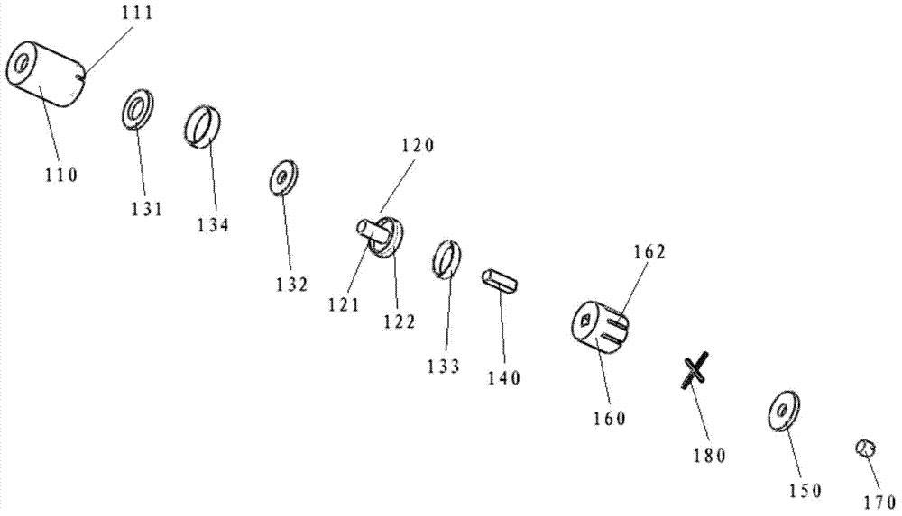
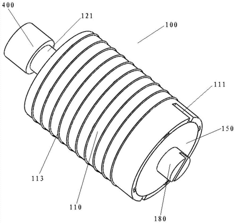
The invention provides a deformable mirror and an actuator component thereof. The actuator component comprises an actuating cylinder, a propeller, a first magnet, a second magnet, a third magnet, a fourth magnet, an actuator and a sealing ring, the propeller is arranged in the actuating cylinder in a front and back linearly movable manner and extends out of the front end wall of the actuating cylinder, the first magnet and the second magnet are arranged in the actuating cylinder along a front and back direction and positioned between the front end wall of the actuating cylinder and the propeller, so that the propeller is pushed backwards by repulsive force of like poles, the like poles of the first magnet and the second magnet are opposite, the third magnet and the fourth magnet are arranged in the actuating cylinder along an internal and external direction and positioned between the propeller and the inner wall of the actuating cylinder, so that the propeller linearly moves front and back by repulsive force of like poles, the like poles of the third magnet and the fourth magnet are opposite, the actuator is arranged in the actuating cylinder to push the propeller to move forwards or allow the propeller to move backwards, and the sealing ring is arranged in the actuating cylinder to seal the rear end of the actuating cylinder. Therefore, according to the actuator component of the deformable mirror, working accuracy can be ensured by the aid of the first magnet and the second magnet with the opposite like poles, and the service life is prolonged.

Description

technical field [0001] The invention relates to the technical field of precision displacement transmission, in particular to a deformable mirror and an actuator assembly thereof. Background technique [0002] Deformable mirrors, also known as deformable mirrors, are mainly used in various adaptive optics systems. As a wavefront correction device to correct wavefront errors, they play an extremely important role in adaptive optics systems. One of the important components, the research and development of the deformable mirror is related to the correction ability and correction accuracy of the whole adaptive optics system. [0003] The deformable mirror compensates the wavefront phase distortion by changing its surface shape, which can be divided into two types: continuous surface shape and discrete surface. The advantage of continuous surface deformation mirror is that it can obtain continuous surface shape and high correction accuracy. The disadvantage is that the deformatio...

Claims


Application Information

Patent Timeline
Patent Type & Authority Applications(China)
IPC IPC(8): G02B26/08
Inventor 黄磊巩马理闫平柳强张海涛康少男
Owner TSINGHUA UNIV
Why Eureka
Try Eureka