Method and device for detecting rear dead zone of vehicle

A blind spot and vehicle technology, applied in the field of vehicle safety, can solve problems such as complex detection methods, low intelligence, and difficulty in judging, and achieve the effects of reducing calculation time, simplifying the installation process, and reducing the amount of calculation

Inactive Publication Date: 2014-03-26
SHENYANG NORMAL UNIV
View PDF8 Cites 6 Cited by
  • Summary
  • Abstract
  • Description
  • Claims
  • Application Information

AI Technical Summary

Problems solved by technology

However, the information content provided by the reversing radar is relatively simple, such as warning lights or sounds, and due to the limitation of the sensitivity and number of sensors and the complexity of the surrounding scenes, delayed alarms or even false alarms may occur
The information provided by the reversing radar is single, and there are the above shortcomings. In view of this situation, in addition to installing the reversing radar, some vehicles are equipped with video sensors to assist the driver to judge the blind area behind the vehicle, which can provide more abundant blind area information. , so that the driver can use the monitor to assist in judging the rear scene conditions when reversing
However, there are still some problems in this video plus radar detection method. If the reversing radar makes a wrong judgment, the driver needs to stop and judge the specific situation of the rear blind area through the monitor in the cab, but it is impossible to find specific obstacles from the monitor screen. , so you have to get out of the car to check the specific situation. Even if the reversing radar is accurate, sometimes it is still difficult to judge some small or hidden obstacles through the monitor screen.
It can be seen that this detection method is actually more complicated than the single sensor detection method
In addition, the reversing video does not further process the video content. What the driver observes through the monitor is only a two-dimensional image of the rear scene. It cannot judge the distance of obstacles like human eyes, and the degree of intelligence is low.

Method used


Image

  • Method and device for detecting rear dead zone of vehicle
  • Method and device for detecting rear dead zone of vehicle
  • Method and device for detecting rear dead zone of vehicle

Examples


Embodiment Construction

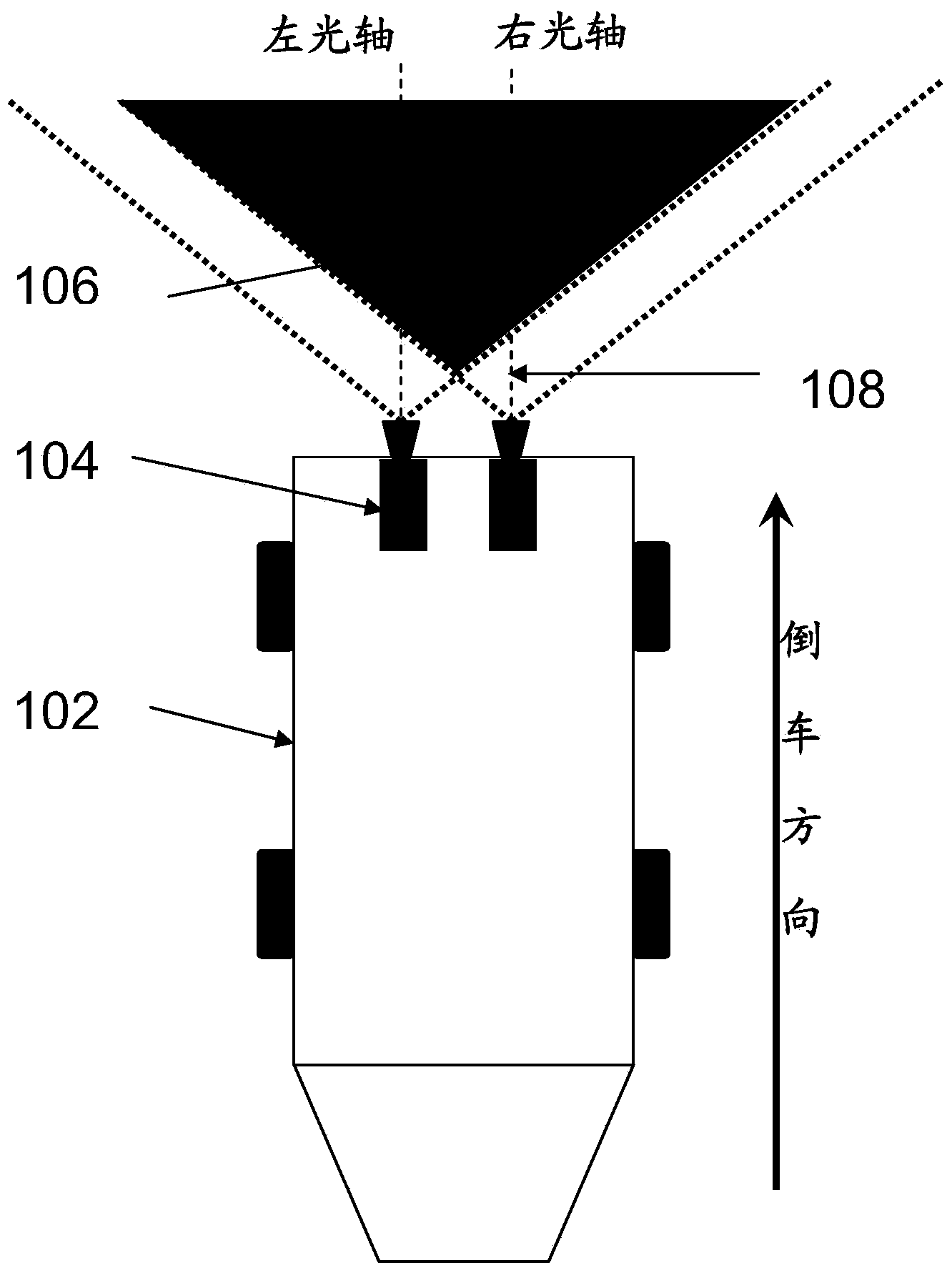
[0019] In this patent, dual video sensors 104 are used for distance measurement, and the two sensors 104 are installed at the rear of the vehicle 102, such as figure 1 As shown, the shaded portion 106 is the area behind the vehicle that the dual sensors can simultaneously observe. The following combination Figure 1-3 Describe the specific implementation principle of this patent.

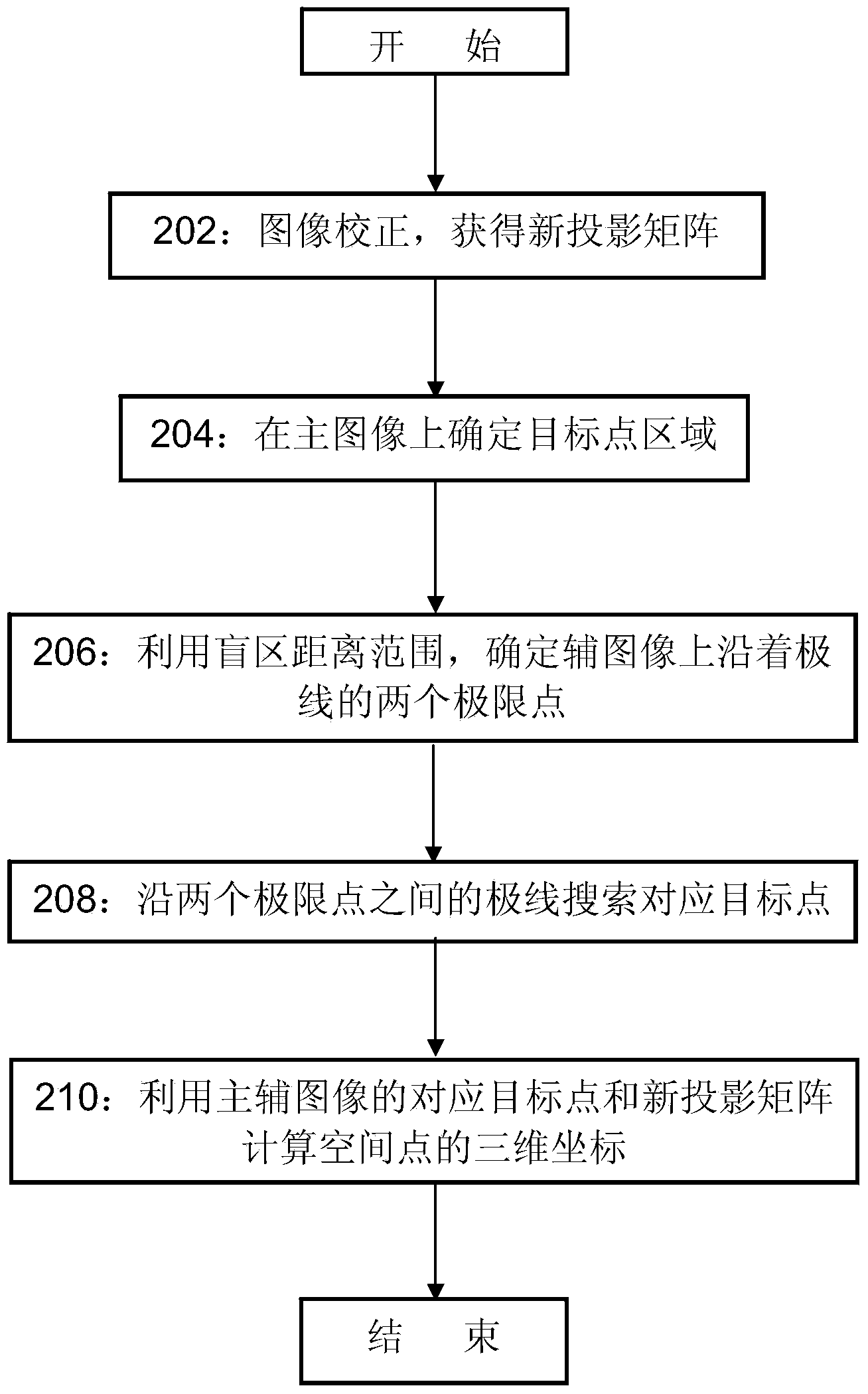
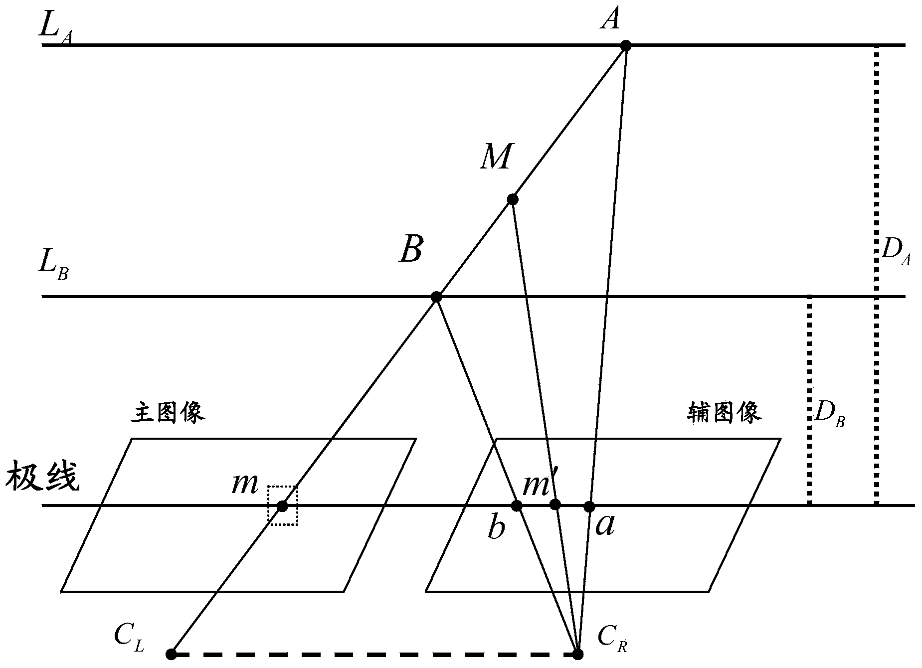
[0020] Step 1 202: Carry out image correction. In principle, the optical axes 108 of the two sensors are required to be parallel, and the imaging planes of the two sensors are required to be coplanar, thus forming image 3 Left and right view configuration shown. But this configuration is difficult to achieve, because in the actual installation, the optical axis of the camera cannot be seen, so accurate adjustments cannot be made. In order to achieve this purpose, the image correction method is used in this patent, so that it is not necessary to accurately realize the installation of parallel op...


PUM


Abstract

The invention relates to the field of vehicle safety and provides an obstacle ranging method for a rear dead zone of a vehicle based on distance restraint. The obstacle ranging method comprises the following steps: firstly, correcting images generated by double sensors to generate main and auxiliary corrected images with parallel optical axes and coplanar images; extracting a target point region containing a target point from the main image and determining a smaller searching range on a pole line of the corrected auxiliary image by using dead zone distance restraint; by taking the target point region as a template, finding a matched target point on the searching range; and calculating a corresponding space point coordinate in a three-dimensional space by using the two corresponding target points on the main and auxiliary corrected images so as to obtain a distance from a space point in a certain distance range behind the vehicle to the vehicle. According to the obstacle ranging method for the rear dead zone of the vehicle based on the distance restraint, the disadvantages of delayed alarm, incorrect alarm and the like of service radar ranging can be avoided; a ranging range can also be expanded and dead zone information is enriched; the intelligent degree of the detection of the rear dead zone of the vehicle is improved.

Description

technical field [0001] The invention relates to the field of vehicle safety, in particular to a method and device for detecting a rear blind spot of a vehicle. Background technique [0002] The blind spot behind the vehicle is an area that the driver cannot observe when reversing. In order to prevent collisions with obstacles or pedestrians when reversing, the usual method is to use on-board radar or reversing video to assist the driver in reversing. Reversing radar generally adopts infrared or radar sensor, which was applied earlier and has been widely installed on almost all vehicles. For example, Audi's side assist system (ASA) detects vehicles within 50 meters behind the side through the radar sensor installed at the rear of the vehicle, and notifies the driver in the form of warning lights. However, the information content provided by the reversing radar is relatively simple, such as warning lights or sounds, and due to the limitation of the sensitivity and number of s...

Claims


Application Information

Patent Timeline
IPC IPC(8): G01C3/00G01C11/08
CPCG01C3/00G01C11/08G01C11/36
Inventor 吴迪周波陈岚峰张旗曲荣发申海马璇
Owner SHENYANG NORMAL UNIV
Why Eureka
Try Eureka