Continuous lifting roller bed

A technology of roller table and lifting bracket, which is applied in the field of conveying line, can solve the problems of heavy financial pressure, achieve the effect of ingenious design concept and meet the needs of material transfer

Active Publication Date: 2014-03-26
MIRACLE AUTOMATION ENG CO LTD
View PDF5 Cites 1 Cited by
  • Summary
  • Abstract
  • Description
  • Claims
  • Application Information

AI Technical Summary

Problems solved by technology

This design and layout method leads to the need for the enterprise to purchase multiple conveyor lines, which brings heavy financial pressure to the enterprise

Method used


Image

  • Continuous lifting roller bed
  • Continuous lifting roller bed
  • Continuous lifting roller bed

Examples


Embodiment Construction

[0011] The specific embodiments of the present invention will be further described below in conjunction with the accompanying drawings.

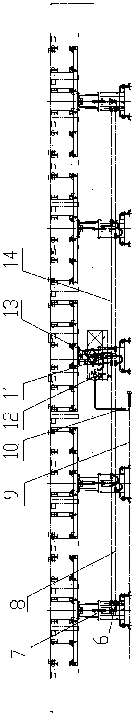
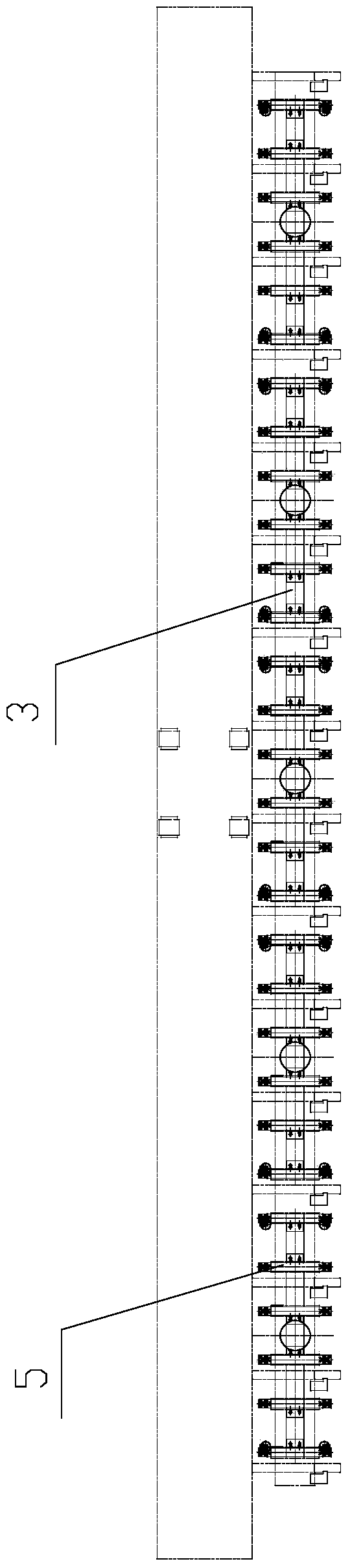
[0012] Figure 1~3 Among them, including lifting bracket 1, smooth motion lifting cylinder 2, top frame 3, rotary guide wheel 4, unpowered roller 5, elbow 6, speed control valve 7, gas pipeline 8, main air pipe 9, ball valve 10, Quick change joint 11, filter pressure reducing valve 12, through solenoid valve 13, return air pipeline 14, etc.

[0013] like Figure 1~3 As shown, the present invention is a continuous lifting roller table, comprising several lifting brackets 1 equidistantly arranged in rows, each lifting bracket 1 is equipped with a smooth motion lifting cylinder 2, and each smooth motion lifting cylinder 2 The gas ports are all connected to the gas transmission pipeline 8, and the gas outlets are all connected to the return gas pipeline 14; the top of the lifting bracket 1 is fixed with a piston sleeve by bolts, and the piston...


PUM


Abstract

The invention relates to a conveying line for use in logistics industry, in particular to a continuous lifting roller bed, comprising a plurality of lifting supports arranged at intervals in a row. Each lifting support is provided with a stable motion lifting cylinder. An air inlet of each stable motion lifting cylinder is communicated with an air pipe, and an air outlet of every stable motion lifting cylinder is communicated with a return air pipe. A piston sleeve is fixed on the top of each lifting support through a bolt. A piston rod is disposed inside the piston sleeve. A push rod of each stable motion lifting cylinder penetrates a top plate of the corresponding lifting support and is connected to one piston rod. A top rack is fixed on the top of each piston rod. Rotating guide wheels are arranged at two ends of the upper portion of each top rack. Two ends of an unpowered roller are rotatably supported in the corresponding rotating guide wheels. The continuous lifting roller bed is ingenious in design; the stable motion lifting cylinders are fixed on the lifting supports, the unpowered rollers can be effectively adjusted in the vertical direction as required so that the transfer requirements of materials in different height levels are met.

Description

technical field [0001] The invention relates to a conveying line used in the logistics industry, in particular to a continuous lifting roller table. Background technique [0002] Logistics transportation centers often need to use various conveying equipment to realize the transfer of materials between various equipment. Most of the existing conveying equipment is a point-to-point structure, that is, one conveying equipment can only realize the transfer between two stations. However, in reality, there are often materials that need to be transferred above or below the two stations that need to be transferred. The existing solution handles this situation by performing double-line layout, that is, separately setting A conveying line to complete the corresponding conveying operations. This design and layout method leads to the need for the enterprise to purchase multiple conveyor lines, which brings heavy financial pressure to the enterprise. Contents of the invention [0003...

Claims


Application Information

Patent Timeline
IPC IPC(8): B65G13/12B65G41/00
Inventor 王瑶瑶蒋正兵
Owner MIRACLE AUTOMATION ENG CO LTD
Why Eureka
Try Eureka