
Vehicle-mounted head-up display

A head-up display and signal display technology, used in vehicle components, circuits or fluid pipelines, transportation and packaging, etc., can solve the problems of unsightly interior of the vehicle body, limited information displayed, and user inconvenience, and shorten the visual blind spot. Time, increase the beauty of the car, reduce the effect of safety hazards

Inactive Publication Date: 2014-03-26
ZHONGSHAN XINQUDONG ELECTRONICS TECH
View PDF5 Cites 11 Cited by
  • Summary
  • Abstract
  • Description
  • Claims
  • Application Information

AI Technical Summary

Problems solved by technology

[0003] However, the design of the head-up display for vehicles on the market today is not perfect, and has its shortcomings. It is necessary to configure a pair of head-up displays of the car model to avoid being unable to be firmly and perfectly configured on the dashboard seat of the car model, which is extremely inconvenient for the user
In addition, the head-up display and its signal units in the prior art are connected by eight to ten signal lines. This is mainly because the head-up display does not have calculation capabilities, so the numerical values ​​must be calculated by the signal unit and then passed through multiple lines. The signal lines are respectively transmitted to the head-up display, and this method is likely to cause inconvenience in configuration and unsightly interior of the car body; and the information that the head-up display in the prior art can display is limited, which corresponds to the current more advanced car models There are shortcomings in application, such as front and rear guidance radar signals, etc., which cannot be displayed by existing technologies, and have practical shortcomings

Method used


Image

  • Vehicle-mounted head-up display
  • Vehicle-mounted head-up display

Examples


Embodiment Construction

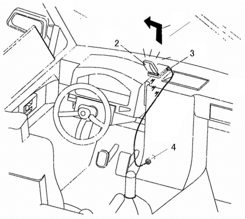
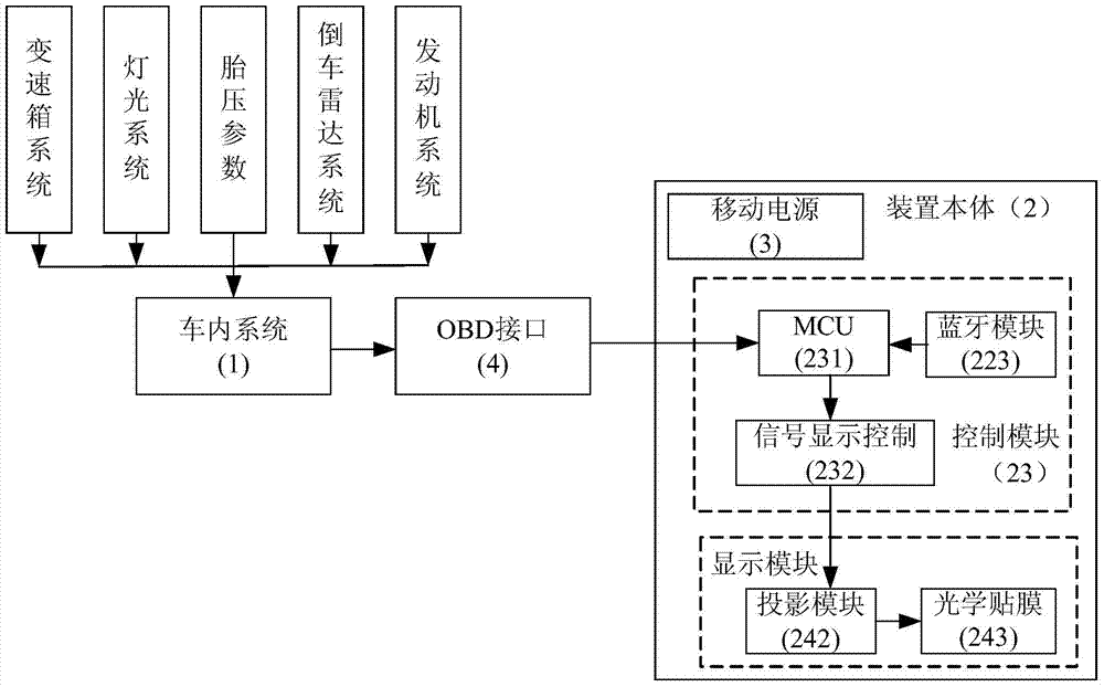
[0018] The present invention relates to a vehicle-mounted head-up display, which includes an in-vehicle system 1, a device body 2, and the mobile power supply 3. The in-vehicle system 1 includes a gearbox system, a lighting system, a tire pressure system, a reversing radar system, and an engine. system, the mobile power supply 3 is electrically connected to the device body 2, and the device body 2 includes a housing 21, a Bluetooth module 223, a control module 23 and a display module 24, and the control module 23 includes MCU231 and signal display control circuit 232. The display module 24 includes a display panel 241, a projection module 242 and an optical film 243. The transmission system, lighting system, tire pressure system, reversing radar system and engine system output terminal is connected with the 4 input ends of the OBD interface, the output end of the OBD interface 4 is connected with the input end of the MCU231, the output end of the MCU231 is connected with the in...


PUM


Abstract

The invention relates to a vehicle-mounted head-up display which comprises an interior vehicle system, a display body and a movable power source. The movable power source is electrically connected with the display body, and the display body comprises a shell, a Bluetooth module, a control module and a display module. The control module comprises an MCU and a signal display control circuit. The display module comprises a display panel, a projection module and an optical film. The output end of a gearbox system, the output end of a light system, the output end of the tire pressure system, the output end of a reversing radar system and the output end of an engine system are connected with the input end of an OBD interface. The output end of the OBD interface is connected with the input end of the MCU, the output end of the MCU is connected with the input end of the signal display control circuit, the output end of the signal display control circuit is connected with the input end of the display panel and the input end of the projection module, and the projection module outputs images and projects the images to the optical film on a windshield.

Description

technical field [0001] The invention relates to the field of automotive supplies, in particular to a vehicle-mounted head-up display. Background technique [0002] Head-Up Display (HUD, Head-Up Display) was originally used in aerospace technology to display flight information by projection on the front window of the aircraft to assist the driver, so that he does not need to constantly look down at the instrument during driving board, thereby increasing the safety of the flight, and as the demand evolves, auxiliary devices used to display driving information are popularized in the prior art, which can bring a high degree of convenience to the driver and help to maintain driving safety. [0003] However, the design of the head-up display for vehicles on the market today is not perfect, and has its shortcomings. It is necessary to configure a pair of head-up displays of the car model to avoid being unable to be firmly and perfectly configured on the dashboard seat of the car m...

Claims


Application Information

Patent Timeline
Patent Type & Authority Applications(China)
IPC IPC(8): B60R11/02B60R16/023
Inventor 高平高小兵王海洋王占磊高琰王方圆陈元喜
Owner ZHONGSHAN XINQUDONG ELECTRONICS TECH
Learn More