
Dynamic perfusion imaging

A technology of perfusion scanning and generation, applied in machine/engine, application, echo tomography, etc., can solve problems such as increasing cumulative radiation dose

Active Publication Date: 2014-03-05
KONINKLJIJKE PHILIPS NV
View PDF11 Cites 7 Cited by
  • Summary
  • Abstract
  • Description
  • Claims
  • Application Information

AI Technical Summary

Problems solved by technology

Taking this a step further, patients undergoing this imaging typically undergo several follow-up imaging procedures, which increases the cumulative radiation dose
Furthermore, simply reducing time interval sampling may introduce errors in the perfusion parameters

Method used


Image

  • Dynamic perfusion imaging
  • Dynamic perfusion imaging
  • Dynamic perfusion imaging

Examples


Embodiment Construction

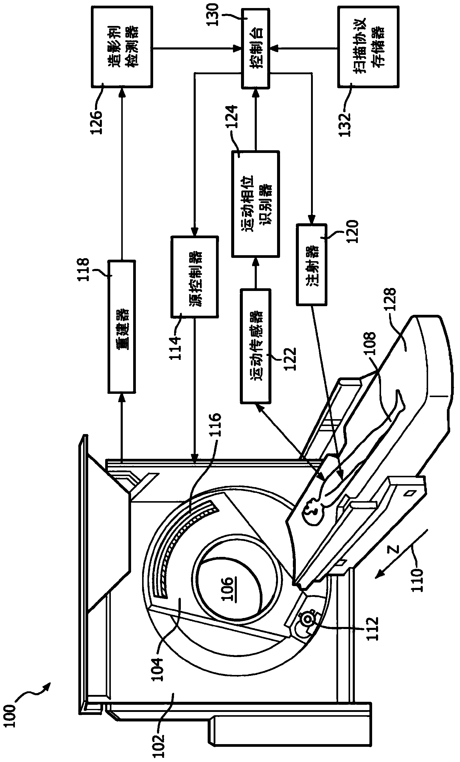
[0021] figure 1 An imaging system 100 is illustrated, such as a computed tomography (CT) scanner.

[0022] The imaging system 100 includes a fixed frame 102 and a rotating frame 104 , and the rotating frame 104 is rotatably supported by the fixed frame 102 . Rotating gantry 104 rotates about an examination region 106 and a portion of an object or subject 108 within the examination region 106 about a longitudinal or z-axis 110 .

[0023] A radiation source 112 , such as an X-ray tube, is supported by the rotating gantry 104 and rotates with the rotating gantry 104 about the examination region 106 . The radiation source 112 emits radiation that is collimated to form a generally fan-shaped, wedge-shaped, or cone-shaped radiation beam that traverses the examination region 106 .

[0024] The source controller 114 controls the radiation source 112 . The control includes activating the source 112 to emit radiation during time-series perfusion imaging to acquire time-frame data. S...


PUM


Abstract

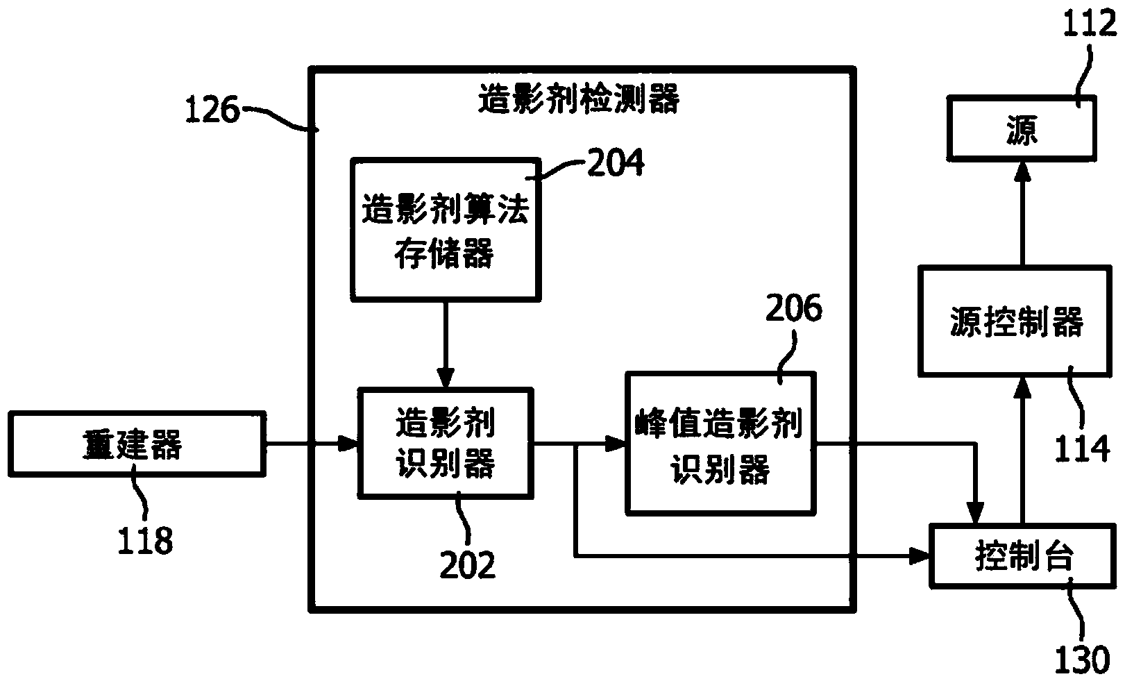
A method includes scanning a region of interest, during a contrast agent based perfusion scan, at a predetermined temporal sampling rate during contrast agent uptake in the region of interest, and generating time frame data indicative of the scanned region of interest. The method further includes identifying a predetermined change in an amount of the contrast agent in the region of interest from the time frame data. The method further includes scanning the region of interest at a lower temporal sampling rate, which is lower than the temporal sampling rate during the contrast agent uptake, in response to identifying the predetermined change in the amount of the contrast agent in the region of interest.

Description

technical field [0001] The following generally refers to dynamic perfusion imaging and is described in conjunction with application to computed tomography (CT); however, the following applies to other imaging modalities as well. Background technique [0002] Perfusion imaging is an imaging technique that captures the transport of an administered contrast agent through vascular tissue of interest, such as blood vessels, and / or an organ such as the heart. Generally, for perfusion imaging, a bolus of contrast agent is administered to a patient and a region of interest, including vascular tissue of interest, is scanned in the patient. The contrast agent causes a temporary increase in x-ray density in the vascular tissue of interest due to the flow of the contrast agent through the vascular tissue. A typical perfusion scan involves acquiring data of the same region over multiple time intervals covering contrast agent arrival, uptake and washout. For cardiac applications, the sc...

Claims


Application Information

Patent Timeline
Patent Type & Authority Applications(China)
IPC IPC(8): A61B6/00
CPCA61B6/503A61B6/542A61B6/507A61B6/486A61B6/481A61B6/00A61B6/5217A61B6/545F04C2270/0421G16H50/30
Inventor M·格拉斯H·施米特
Owner KONINKLJIJKE PHILIPS NV
Learn More