
Electric cabinet locking device

A technology for electric machines and cabinet locks, which is applied in the direction of fixing devices, mechanical equipment, etc., and can solve problems such as inconvenient operation

Inactive Publication Date: 2014-02-26
XIAN KUNLUN IND GRP
View PDF7 Cites 2 Cited by
  • Summary
  • Abstract
  • Description
  • Claims
  • Application Information

AI Technical Summary

Problems solved by technology

[0004] In order to overcome the inconvenient operation of the existing electrical cabinet locking device

Method used


Image

  • Electric cabinet locking device
  • Electric cabinet locking device
  • Electric cabinet locking device

Examples


Embodiment Construction

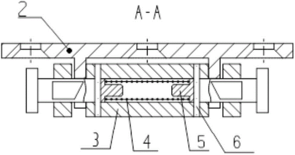
[0024] The following examples refer to Figure 1-13 . The electrical cabinet locking device of the present invention includes a lock base 1 and a latch 2 , and the latch 2 includes a lock body 3 , a spring 4 , a latch 5 and a pin 6 . Wherein the lock seat 1 is a part, and the latch 2 is a component.

[0025] The material of the lock seat 1 is 45 steel, which is quenched and tempered.

[0026] In order to meet the locking requirements, the lock seat 1 is designed with a locking hole ① and a fork ②.

[0027] A spring 4 , a bayonet pin 5 and a pin 6 are installed on the lock body 3 of the bayonet lock 2 .

[0028] The material of the lock body 3 is 45 steel, which is quenched and tempered.

[0029] The lock body 3 is the installation body of the spring 4, the bayonet pin 5 and the pin 6. The lock body 3 is designed with the first installation hole 7 for installing the spring 4 and the bayonet pin 5, and the second installation hole 8 for the installation pin 6, and is designe...


PUM


Abstract

The invention discloses an electric cabinet locking device and aims to solve the technical problem that the existing electric cabinet locking device is inconvenient to operate. According to the technical scheme, the electric cabinet locking device is composed of a lock base and a retainer lock. The lock base is provided with two prongs and a transverse locking hole behind the prongs. A lock body of the retainer lock is provided with a first mounting hole. A spring is mounted in the center of the first mounting hole. Clamp pins capable of sliding in the mounting hole are fitted to two ends of the first mounting hole respectively. After a pin fixed on the lock body penetrates an elongated hole of the clamp pin, the clamp pin is allowed to only slide left and right in the lock body without slipping off. Two ends of the lock body are provided with two locking grooves used for accommodating the two prongs. The lock base is fixed on a frame. A clamp lock part is fixed on the lower portion of a case. The center of the lock base is horizontally level with the center of the retainer lock, and the lock base and the retainer lock are in bilateral alignment symmetry. To lock the case to the frame, the retainer lock is pushed into the lock base and locked to the lock base through the spring and the clamp pin. To pull out and unlock the case, the clamp is bidirectionally compressed. With the electric cabinet locking device, an electric cabinet can be reliably locked and conveniently unlocked.

Description

technical field [0001] The invention relates to a locking device, in particular to an electrical cabinet locking device. Background technique [0002] The locking mechanism of each combination in the existing electric cabinet adopts the chassis or the combination panel to connect and fasten with the frame through screws, so as to realize locking and fixing. [0003] Existing electrical cabinets generally adopt a fastening method in which screws pass through the panel, and the combined panel is pressed against the cabinet body by tightening the screws to achieve fastening and locking. Although the locking effect of the screw connection locking method is relatively reliable, it is time-consuming and laborious, and the fastening and releasing operations are inconvenient. Contents of the invention [0004] In order to overcome the disadvantage of inconvenient operation of the existing electrical cabinet locking device. The invention provides a locking device for an electrica...

Claims


Application Information

Patent Timeline
Patent Type & Authority Applications(China)
IPC IPC(8): F16B1/04
Inventor 李燕宗李晓琼汤天启尹伦刚李成龙王万杰
Owner XIAN KUNLUN IND GRP
Learn More