Front spring front support cross beam assembly

A technology of beam assembly and front bracket, applied in the directions of substructure, transportation and packaging, vehicle components, etc., to achieve the effect of improving bending and torsion resistance, being easy to manufacture, and strengthening beams

Inactive Publication Date: 2014-02-19
SINO TRUK JINAN POWER
View PDF6 Cites 2 Cited by
  • Summary
  • Abstract
  • Description
  • Claims
  • Application Information

AI Technical Summary

Problems solved by technology

Most of the existing front spring and front bracket beams adopt welded or stamped structure, which has a high failure rate and cannot meet the actual needs

Method used


Image

  • Front spring front support cross beam assembly
  • Front spring front support cross beam assembly

Examples


Embodiment Construction

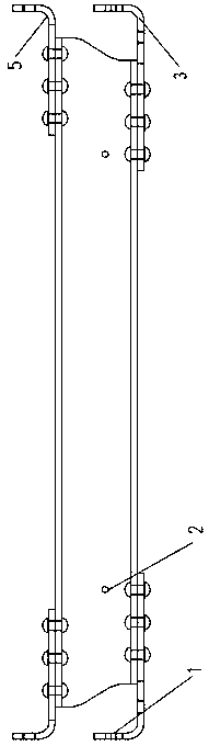
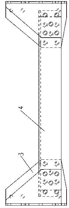
[0017] Such as figure 1 with figure 2 As shown, the front spring front bracket beam assembly includes a beam 4 made of a section of channel steel, two upper wing plates 5 and two lower wing plates 3 . The beam includes an upper leg board and a lower leg board, and the upper leg board is positioned right above the lower leg board. Both the upper wing plate and the lower wing plate are bent upward at 90° and both include a vertical portion and a horizontal flat portion. The two upper wing plates are arranged oppositely and their upright parts are located outside the horizontal flat part. The horizontal flat parts of the two upper wing plates are respectively riveted with the two ends of the upper leg plate by rivets, the two lower wing plates are arranged oppositely and their vertical parts are located outside the horizontal flat parts, and the horizontal flat parts of the two lower wing plates are respectively connected with the two ends of the lower leg plate. The parts a...


PUM


Abstract

The invention provides a front spring front support cross beam assembly. The front spring front support cross beam assembly comprises a cross beam formed by a section of box iron, two upper wing boards and two lower wing boards. The cross beam comprises an upper leg board and a lower leg board, the upper leg board is arranged over the lower leg board, the upper wing boards and the lower wing boards are all bent boards bent upwards by 90 degrees and respectively comprise a vertical portion and a transverse portion, the two upper wing boards are arranged opposite to each other, the vertical portions of the two upper wing boards are arranged on the outer sides of the transverse portions of the two upper wing boards, the transverse portions of the two upper wing boards are riveted to the two end portions of the upper leg board respectively through rivets, the two lower wing boards are arranged opposite to each other, the vertical portions of the two lower wing boards are arranged on the outer sides of the transverse portions of the two lower wing boards, the transverse portions of the two lower wing boards are riveted to the two end portions of the lower leg board respectively through rivets, the two upper wing boards are arranged over the two lower wing boards respectively and correspondingly, and the two upper wing boards and the two lower wing boards are respectively provided with a bolt hole used for being connected with frame bolts. The front spring front support cross beam assembly can play the role in reinforcing the cross beam of a frame, effectively support a left front spring front support and a right front spring front support, and greatly improve the bending-resisting capability of a whole vehicle chassis.

Description

technical field [0001] The invention relates to a crossbeam assembly of a front spring and a front bracket. Background technique [0002] The working conditions of the mining truck are relatively harsh, and the vehicle body is relatively wide, which makes the force on the front bracket of the front spring larger. Most of the existing front spring and front bracket beams adopt welded or stamped structures, which have a high failure rate and cannot meet actual needs. Contents of the invention [0003] The technical problem to be solved by the present invention is to provide a front spring and front bracket beam assembly. [0004] In order to solve the problems of the technologies described above, the technical solution of the present invention is: [0005] A crossbeam assembly of a front spring and front bracket, including a crossbeam made of a section of channel steel, two upper wing plates and two lower wing plates, the crossbeam includes an upper leg plate and a low...

Claims


Application Information

Patent Timeline
Patent Type & Authority Applications(China)
IPC IPC(8): B62D21/00
Inventor 王玥张志刚苑立宽
Owner SINO TRUK JINAN POWER
Why Eureka
Try Eureka