
Phased array beamforming method based on airborne equipment

A technology of beamforming and airborne equipment, which is applied in radio wave measurement systems, radio wave reflection/reradiation, utilization of reradiation, etc., can solve the deviation between the actual feed phase and the theoretical value, the reduction of antenna beam pointing accuracy, the phase Control array pointing accuracy decline and other issues, to achieve high accuracy, improve anti-interference ability, light weight effect

Active Publication Date: 2015-11-18
四川九洲空管科技有限责任公司
View PDF3 Cites 3 Cited by
  • Summary
  • Abstract
  • Description
  • Claims
  • Application Information

AI Technical Summary

Problems solved by technology

The beam synthesis method in the prior art makes the angle measurement accuracy not high. The key to the application of angle measurement technology is to generate a sum and difference beam that meets the requirements. Therefore, to obtain high angle measurement accuracy, the performance of the synthesized beam must be improved.
For example, the existence of phase quantization error makes the actual feed phase of each antenna unit of the phased array antenna deviate from the theoretical value, resulting in a decrease in the antenna beam pointing accuracy; at the same time, phase quantization makes the beam of the main lobe broaden, the gain is reduced, and the lost energy is dispersed to The removal of side lobes causes the level of side lobes to increase, further reducing the pointing accuracy of the phased array

Method used


Image

  • Phased array beamforming method based on airborne equipment
  • Phased array beamforming method based on airborne equipment
  • Phased array beamforming method based on airborne equipment

Examples


Embodiment Construction

[0024] The specific implementation manners of the present invention will be described in detail below in conjunction with the accompanying drawings.

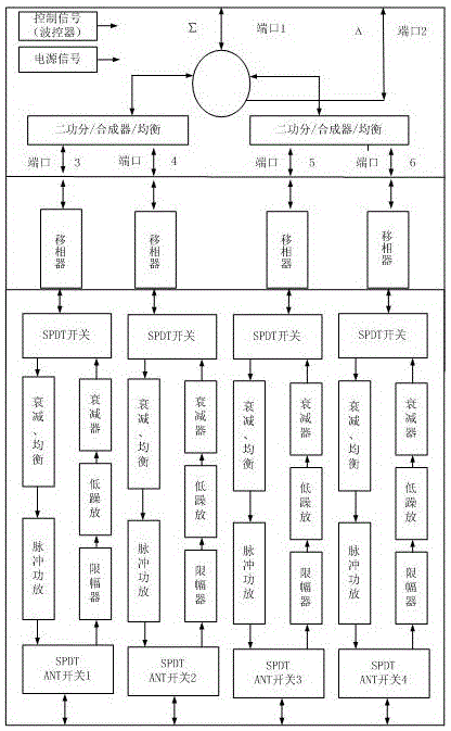
[0025] In the present invention, the phased array antenna is used to send an inquiry signal to the space and receive a response signal from the space at the same time. Such as figure 1 The phased array schematic is shown.

[0026] The invention discloses a phased array beam synthesis method based on airborne equipment, which specifically includes: dividing the phased array antenna array unit into left and right antenna array units; feeding the left and right antenna array units in the same phase, and The sum beam is obtained by adding the pattern functions formed by the right and right antenna array units; feeding the left and right antenna array units in reverse phase, and subtracting the pattern functions formed by the left and right antenna array units to obtain a difference beam. By adopting the above method, the sum beam ...


PUM


Abstract

The invention relates to the technical field of phased-array antennae and discloses a phased array beamforming method based on airborne equipment. The method comprises the steps of dividing a phased-array antenna array element into a left antenna array element and a right antenna array element; carrying out in-phase feeding on the left antenna array element and the right antenna array element, and adding a pattern function formed by the left antenna array element and a pattern function formed by the right antenna array element together to obtain a sum beam; carrying out anti-phase feeding on the left antenna array element and the right antenna array element, and carrying out subtraction on a pattern function formed by the left antenna array element and a pattern function formed by the right antenna array element to obtain a difference beam. According to the method, the application of the phased array beamforming method in the airborne equipment is achieved; the sum beam and the difference beam can be generated easily, and beam scanning can be achieved; the application of the phased-array antennae enables scanning to be achieved more flexibly, anti-jamming capacity to be high, and reliability to be high; meanwhile, the anti-jamming capacity of a system is improved by means of the sidelobe suppression technique.

Description

technical field [0001] The invention relates to the technical field of phased array antennas, in particular to an airborne device-based phased array beam synthesis method. Background technique [0002] Secondary Surveillance Radar (SRR) has been widely used in air traffic control, friend-or-foe identification, etc. Secondary radar is an electronic device that transmits signals and receives response signals to obtain cooperative target information. Traditional secondary radar usually adopts the working mode of mechanical scanning. [0003] Traditional secondary radar antennas use fixed beams or mechanical scanning. The mechanical scanning speed is slow, and it is difficult to ensure tracking performance. The corresponding mechanical inertia is large, and the shock resistance and vibration resistance are poor. The phased array radar antenna is different from the mechanical scanning radar antenna. The beam pointing is changed by changing the signal phase relationship of each a...

Claims


Application Information

Patent Timeline
Patent Type & Authority Patents(China)
IPC IPC(8): G01S7/41G01S7/36
CPCG01S7/2813G01S13/762
Inventor 舒荣李双成滕新友
Owner 四川九洲空管科技有限责任公司
Learn More