
Device for separating domestic sewage

A domestic sewage and air bag technology, which is applied in the direction of filtration separation, separation method, fixed filter element filter, etc., can solve the problems of large space occupation, low work efficiency, difficult arrangement, etc., and achieve small space occupation, simple structure and convenient operation Effect

Active Publication Date: 2014-02-05
WUHAN UNIV OF TECH
View PDF7 Cites 18 Cited by
  • Summary
  • Abstract
  • Description
  • Claims
  • Application Information

AI Technical Summary

Problems solved by technology

[0002] Due to the increasingly stringent environmental requirements, the application of mobile sewage treatment vehicles in the field of sewage treatment is becoming more and more extensive. However, the solid-liquid separation devices currently used in sewage treatment vehicles are generally complex in structure and low in efficiency. , or take up a lot of space and are not easy to arrange
For example, septic tank sewage treatment equipment, the utility model of authorized announcement number CN 201473395 U discloses a kind of septic tank sewage treatment equipment, the sewage is separated through the principle of filter screen interception, vacuum suction and centrifugal sedimentation, vacuum suction The method of separating solid and liquid is not thorough, the separated object will still contain more water, the energy consumed by centrifugal sedimentation is high, and it is not easy to treat a large amount of sewage at the same time; Device, authorized announcement number CN 202805696 U, another example is a sewage and dirt vacuum pumping separation device, authorized announcement number CN 202899291 U, etc., these are not easy to install on the sewage treatment vehicle for mobile operation

Method used


Image

  • Device for separating domestic sewage
  • Device for separating domestic sewage
  • Device for separating domestic sewage

Examples


Embodiment Construction

[0016] The present invention will be further described below in conjunction with accompanying drawing.

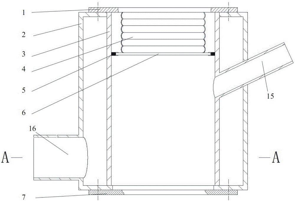
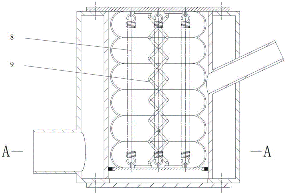
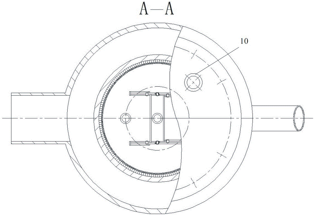
[0017] Such as figure 1 , 2 , 3, which is a structural schematic diagram of an embodiment provided by the present invention, as can be seen from the figure, it includes a filter cartridge 2, the filter cartridge 2 is open at both ends, and a filter screen 3 is arranged in the filter cartridge 2. The two ends of the net 3 are connected with the two ends of the filter cartridge 2, and an airbag extruding mechanism is arranged in the filter mesh 3. The airbag extruding mechanism includes an airbag 4, an airbag cover plate 1, an airbag bottom plate 6, and one end of the airbag 4 is connected to the airbag The cover plate 1 is connected, the airbag cover plate 1 is fixedly connected with one end of the filter cartridge 2, the other end of the airbag 4 is connected with the airbag bottom plate 6, and a wiper is arranged on the outer peripheral edge of the airbag bottom plate 6, ...


PUM


Abstract

The invention discloses a device for separating domestic sewage. The device comprises a filter drum, wherein two ends of the filter drum are respectively in an opening shape, a filter net is arranged inside the filter drum, two ends of the filter net are connected with two ends of the filter drum, an airbag squeezing mechanism is arranged inside the filter net, the airbag squeezing mechanism comprises an airbag, an airbag cover plate and an airbag soleplate, one end of the airbag is connected with the airbag cover plate, the airbag cover plate is fixedly connected with one end of the filter drum, the other end of the airbag is connected with the airbag soleplate, the periphery of the airbag soleplate is in slide fit with the inner wall of the filter net, a spring is arranged between the airbag cover plate and the airbag soleplate inside the airbag, the other end of the filter drum is provided with a filter drum bottom cover, and the airbag cover plate is provided with an inlet-exhaust hole. The device is simple in structure, convenient to operate and high in efficiency; both the stretching and retraction processes of the airbag are completed inside the filter net, and the occupied space is small.

Description

technical field [0001] The invention relates to a device for separating domestic sewage. Background technique [0002] Due to the increasingly stringent environmental requirements, the application of mobile sewage treatment vehicles in the field of sewage treatment is becoming more and more extensive. However, the solid-liquid separation devices currently used in sewage treatment vehicles are generally complex in structure and low in efficiency. , or take up a lot of space and are not easy to arrange. For example, septic tank sewage treatment equipment, the utility model of authorized announcement number CN 201473395 U discloses a kind of septic tank sewage treatment equipment, the sewage is separated through the principle of filter screen interception, vacuum suction and centrifugal sedimentation, vacuum suction The method of separating solid and liquid is not thorough, the separated object will still contain more water, the energy consumed by centrifugal sedimentation is ...

Claims


Application Information

Patent Timeline
Patent Type & Authority Applications(China)
IPC IPC(8): B01D29/35B01D29/64
Inventor 华林徐杨坤何耀华李晚霞杨灿
Owner WUHAN UNIV OF TECH
Learn More