A self-priming device for a centrifugal pump

The technology of self-priming device and centrifugal pump is applied to the components, pump, driving pump and other directions of pumping device for elastic fluid, which can solve the problems of increasing the difficulty of control operation, occupying space, and increasing the axial length of the pump body, etc. Achieve the effect of avoiding unstable work, simple and compact overall structure, and ensuring work reliability

Active Publication Date: 2015-12-23
HEFEI UNIV OF TECH +1
View PDF9 Cites 0 Cited by
  • Summary
  • Abstract
  • Description
  • Claims
  • Application Information

AI Technical Summary

Problems solved by technology

However, the congenital defects of the vertical pump's own structure cannot be underestimated: since the pump impellers of the vertical pump are mostly located above the water surface, and they do not have or only have a very weak self-priming function when they are started, they are mostly in the centrifugal pump. When the pump is started, it is necessary to artificially fill the pump impeller chamber with water to form a vacuum environment in the pump impeller chamber, so as to achieve the suction purpose of the centrifugal pump. The complexity of the start-up steps obviously greatly affects its actual operation. operating efficiency
Later, people began to install an external vacuum self-priming device on the basis of the existing centrifugal pump to achieve the purpose of strong self-priming during the pump start-up stage; however, due to the need to arrange an additional external vacuum self-priming device, not only when installing Sometimes it will occupy the limited space of the ship, which makes the original limited space of the ship or the chemical industry more stretched. At the same time, the pipeline layout between the vacuum self-priming device and the centrifugal pump is often messy and difficult to sort out. It is necessary to distract the opening and closing of the two sets of devices, which increases the difficulty of control operation when starting.
In addition, during the installation of vertical pumps, the bearing installation of the pump shaft is essential, and the bearings need an additional bearing fixing support as their fixing base, which will inevitably lead to an increase in the axial length of the pump body, thus occupying Part of the limited space affects the smooth operation of the pump equipment; at the same time, because the bearings need to be lubricated and cooled, traditional vertical pumps often need to be equipped with an additional lubrication and flushing system, which greatly increases the difficulty and difficulty of daily maintenance of the entire pump system. The cost

Method used


Image

  • A self-priming device for a centrifugal pump
  • A self-priming device for a centrifugal pump
  • A self-priming device for a centrifugal pump

Examples


Embodiment Construction

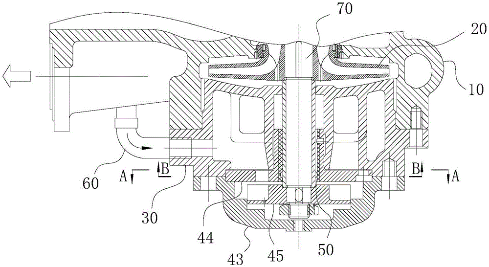
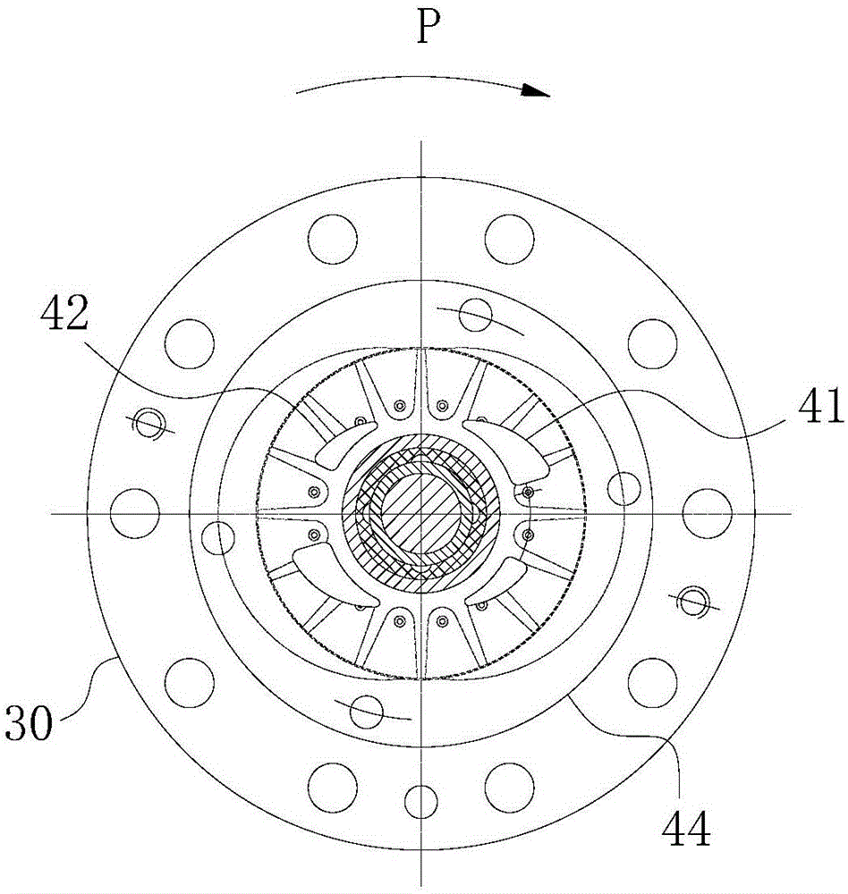
[0027] For ease of understanding, the following combination Figure 1-4 Concrete structure and workflow of the present invention are described as follows:

[0028] Such as figure 1As shown, the present invention includes a vacuum pump, a pump body 10 and a pipeline 60 . The vacuum pump and the pump body 10 are sequentially connected in series through the integrated pump shaft structure 70 formed by the pump shaft and the rotating shaft, that is, after the head end of the integrated pump shaft structure 70 is connected to the aforementioned driving end, it is then extended from the pump body 10 The middle part of the pump chamber passes through and is fixed by the spacer 30. The tail end of the integrated pump shaft structure 70 constitutes the rotating shaft of the vacuum pump so as to be fixedly connected to the self-priming impeller 45, and the shaft between the head end and the middle part of the integrated pump shaft structure 70 The shaft forms a fixed section of the im...


PUM


Abstract

The invention belongs to the field of centrifugal pumps, and particularly relates to a self-absorption device provided with a combined structure and used for a centrifugal pump. The self-absorption device comprises a pump body and a pump shaft part. One end of the pump shaft part is provided with a driving assembly, and the pump shaft part is provided with an impeller part. The self-absorption device further comprises a vacuum self-absorption assembly which is arranged at the other end, opposite to the end where the power driving end is located, of the pump shaft part. The negative pressure pumping end of the vacuum self-absorption assembly is communicated with the water outlet end of the pump body, the air outlet end of the vacuum self-absorption assembly is communicated with the water inlet end of the pump body, and a rotating shaft of the vacuum self-absorption assembly and the axis of the pump shaft part are coaxially arranged. The self-absorption device further comprises a separating part which is used for sealing a pump cavity of the pump body, and bearing fit is formed among / between he pump shaft part and / or the rotating shaft and the separating part. The self-absorption device is reasonable and practical in structural design and easy and convenient to operate, and the actual size of the self-absorption device is effectively reduced while working efficiency is ensured.

Description

technical field [0001] The invention belongs to the field of centrifugal pumps, in particular to a self-priming device for centrifugal pumps with a combined structure. Background technique [0002] In the water supply and drainage system of ships and in the chemical industry, centrifugal self-priming pumps are commonly used as pumps, and their universality goes without saying; however, due to the relatively narrow and concentrated space of ships and the high cost of pump body materials for chemical pumps, the volume Compact and relatively small vertical pumps are widely used. However, the congenital defects of the vertical pump's own structure cannot be underestimated: since the pump impellers of the vertical pump are mostly located above the water surface, and they do not have or only have a very weak self-priming function when they are started, they are mostly in the centrifugal pump. When the pump is started, it is necessary to artificially fill the pump impeller chamber...

Claims


Application Information

Patent Timeline
Patent Type & Authority Patents(China)
IPC IPC(8): F04D9/04F04D29/046F04D29/06
Inventor 石海峡李强何玉杰吴进钱巫建波李跃张军辉
Owner HEFEI UNIV OF TECH
Why Eureka
Try Eureka