Roller screw rod with spacing bodies

A technology of roller screws and rollers, which is applied in the direction of belts/chains/gears, mechanical equipment, transmission devices, etc., and can solve problems such as increased distance between rollers, stuck roller screws, and reduced load capacity. Achieve the effects of shortening assembly time, saving processing costs, and easy assembly

Active Publication Date: 2014-01-15
HIWIN TECH
View PDF7 Cites 4 Cited by
  • Summary
  • Abstract
  • Description
  • Claims
  • Application Information

AI Technical Summary

Problems solved by technology

[0004] First, since the roller is fixed to a cage with a single diagonal line, the cage of the roller must be able to keep the non-loaded surfaces on both sides without contact, but the roller will generate a torque on the cage when it rotates Force, so that the rollers will deflect toward the two non-load surfaces that are not in contact, making the position of the retainer difficult to fix and easy to fall off, and the fall of the retainer will cause the problem of the roller screw being stuck;
[0005] Second, since the above-mentioned rollers are fixed to a cage with a single diagonal line, in order for the cage to be positioned stably, the rollers need to have a certain thickness and material stress to prevent the rollers from falling off easily, but the cage is designed too thick But it will make the distance between the rollers larger, resulting in the reduction of the overall number of rollers and the reduction of the load capacity;
[0006] Third, the design of the retainer is not easy to assemble. Even after the rollers and the retainer are assembled, it is even more difficult to fit between the screw and the nut, and the retainer needs to be embedded in the tooth track. It takes a lot of time to place the position, so the manufacturing cost of the roller screw is increased a lot

Method used


Image

  • Roller screw rod with spacing bodies
  • Roller screw rod with spacing bodies
  • Roller screw rod with spacing bodies

Examples


Embodiment Construction

[0063] In order to further explain the technical solution of the present invention, the present invention will be described in detail below through specific examples.

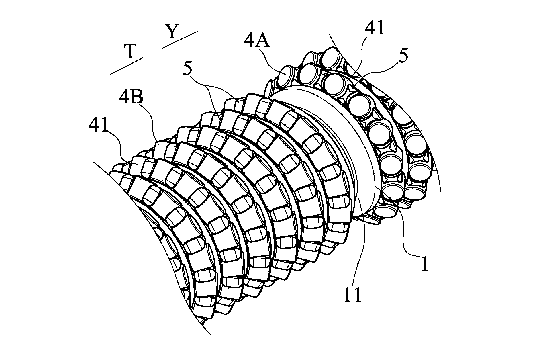
[0064] First of all, the spacer structure of the first preferred embodiment of the present invention is described, please refer to Figure 4A to Figure 4C As shown, it is a schematic diagram of the design process of the spacer of the present invention. There are two types of arrangement of the rollers in the existing common roller screw. One is: the axes of two adjacent rollers are arranged in the same direction, and the other is: The axes of two adjacent rollers are arranged in different directions, and the angle between the two axes is 90 degrees. This arrangement is as follows: Figure 4A shown. The structural design of the spacer 5 of the present invention comes from the arrangement of the axes of the two adjacent rollers in different directions. This is because the rollers arranged in different directions...


PUM


Abstract

The invention discloses a roller screw rod with spacing bodies. The roller screw rod with the spacing bodies comprises a screw rod body, a screw nut, a backflow piece, a plurality of rollers and a plurality of spacing bodies. The screw nut is arranged on the screw rod in a sleeved mode, and a load path is formed between the screw rod body and the screw nut. The backflow piece is arranged on the screw nut and is provided with a backflow channel connected with the load path. The rollers are arranged in the load path, and each roller is provided with an external diameter face. The spacing bodies are arranged between every two rollers, the two sides of each spacing body are respectively provided with a maintaining concave part, and each maintaining concave part is provided with a vertical face and two slant faces. When the rollers are in the load path, the external diameter face of each roller is in contact with one of the slant faces, and when the rollers are in the backflow channel, the external diameter face of each roller is in contact with one vertical face. Thus, the roller screw rod with the spacing bodies has the effects that assembling is easy, the load capacity of the roller screw rod can be enhanced, and mutual interference with one another among the rollers can be avoided.

Description

technical field [0001] The invention relates to a transmission mechanical assembly, in particular to a roller screw with a spacer. Background technique [0002] Today's roller screws or linear slide rails are used more and more in industry. In addition to the high-precision effects of linear transmission, others have low friction loss rate, high energy conversion rate, low noise and high rigidity. Therefore, the importance of roller screws or linear slides for various industrial application tools today is self-evident. One of the rolling elements commonly used in the current roller screw or linear slide rail design is the roller. In order to allow the rollers between the elements to continuously circulate and relieve stress, many improved designs will install cages on the rollers; but Different roller cage designs have their defects. Therefore, how to develop and improve roller cages to produce more competitive products has naturally become the focus of the industry. [00...

Claims


Application Information

Patent Timeline
IPC IPC(8): F16H25/22
CPCF16H25/2247F16H2025/2271F16H25/2261F16H2025/2276
Inventor 刘宪正吴文加
Owner HIWIN TECH
Why Eureka
Try Eureka