
Coil antenna unfolding structure

A loop antenna and parallelogram technology, applied in the field of satellite antennas, can solve problems such as structural damage, achieve the effect of reducing the diameter of the fold and ensuring reliability

Active Publication Date: 2014-01-01
XIAN INSTITUE OF SPACE RADIO TECH
View PDF3 Cites 9 Cited by
  • Summary
  • Abstract
  • Description
  • Claims
  • Application Information

AI Technical Summary

Problems solved by technology

Therefore, on the one hand, when the antenna is retracted and the gap between the rods is narrowed, the tangential projections of the upper crossbar and the lower crossbar overlap, and the oblique rod is in an S-shaped bending stress state when the loop antenna is retracted, which will lead to the skew of the loop antenna. The rod is deformed in the state of S-shaped stress when the loop antenna is closed, such as Figure 5 As shown, structural damage is prone to occur under the action of launch load
On the other hand, the diameter of the antenna after retracting is not reduced enough

Method used


Image

  • Coil antenna unfolding structure
  • Coil antenna unfolding structure
  • Coil antenna unfolding structure

Examples


Embodiment Construction

[0019] The present invention will be further described below in conjunction with drawings and embodiments.

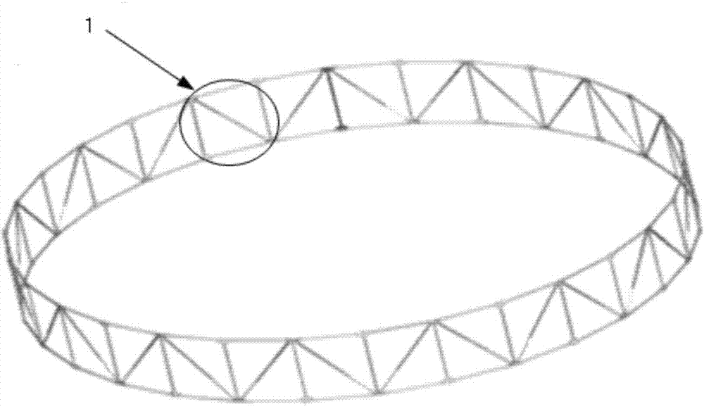
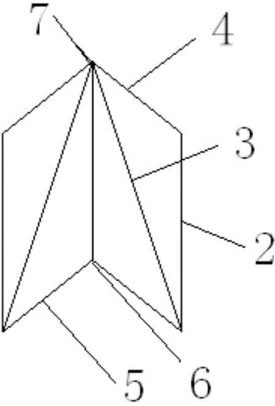
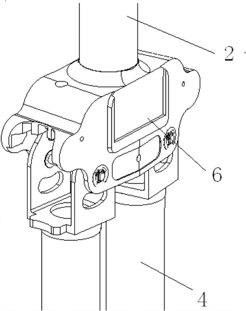
[0020] A loop antenna unfolding structure of the present invention is a closed polygonal ring formed by connecting multiple parallelogram units 1 with the same structure through hinges, and each parallel unit has two vertical rods (2) and a diagonal rod (3), an upper cross bar (4) and a lower end cross bar (5) are arranged and installed in layers to reduce the folded size of the unfolded structure of the loop antenna; each parallelogram unit 1 includes two vertical bars 2, a Slant bar 3, an upper end cross bar 4 and a lower end cross bar 5, two adjacent parallelogram units 1 share one vertical bar 2; at the three-point hinge 6 where the vertical bar 2 intersects with two horizontal bars, The vertical bar 2 and the horizontal bar are misplaced in the horizontal direction, the vertical bar 2 is on the inner layer, and the two horizontal bars are on the outer layer; at the...


PUM


Abstract

The invention discloses a coil antenna unfolding structure which is a closed polygonal ring formed by connecting a plurality of parallelograms (1) with the same structure through a hinge. Each parallelogram (1) comprises two vertical rods (2), a slanting rod (3), an upper-end transverse rod (4) and a lower-end transverse rod (5). Every two adjacent parallelograms (1) share one vertical rod (2). The vertical rods and the slanting rod are arranged on the same layer at the hinge position of the rods, the upper-end transverse rod and the lower-end transverse rod are arranged on the same layer, multi-layer overlapping of the rods in the radial direction of a coil antenna is achieved, and the folded diameter of the unfolding structure of the coil antenna is effectively decreased through the layered arrangement of the rods. In addition, due to the fact that the rods on the same layer cannot be overlapped, the vertical rod, the slanting rod, the upper-end transverse rod and the lower-end transverse rod are all in the vertical free unstressed state, and the reliability of the folded structure of the antenna is ensured.

Description

technical field [0001] The invention belongs to the technical field of satellite antennas, in particular to a space-borne loop antenna structure. Background technique [0002] The unfolding structure of the loop antenna is the moving part of its folding and unfolding, which also determines the size of the loop antenna’s folding and unfolding, which will affect the lightweight and miniaturization of the satellite to a certain extent. The current unfolded structure of the loop antenna is a plurality of parallelogram units 1 with the same structure through the included angle 12 0 A closed polygonal ring connected by hinges, such as figure 1 shown. Each parallelogram unit 1 is made up of vertical bar 2, oblique bar 3, upper end cross bar 4 and lower end cross bar 5, as figure 2 shown. The folded diameter of the loop antenna is an important index for the structural design of the loop antenna, and reducing the folded diameter of the loop antenna has always been an important c...

Claims


Application Information

Patent Timeline
Patent Type & Authority Applications(China)
IPC IPC(8): H01Q7/02
Inventor 冯涛王波马小飞华岳段浩刘路
Owner XIAN INSTITUE OF SPACE RADIO TECH
Learn More