Method for establishing address mapping table of solid-state memory

A solid-state storage and correspondence table technology, applied in memory address/allocation/relocation, memory systems, instruments, etc., can solve the problem of waiting for a long time to receive, reducing the access efficiency of solid-state storage devices, and time-consuming long and other issues

Inactive Publication Date: 2014-01-01
LITE ON TECH CORP
View PDF3 Cites 3 Cited by
  • Summary
  • Abstract
  • Description
  • Claims
  • Application Information

AI Technical Summary

Problems solved by technology

[0014] However, due to the large amount of data in the L2P table, it takes too long for the non-volatile memory 105 to completely load the L2P table into the cache memory 107 after the solid-state storage device 10 is powered on, so that the host 12 needs to wait for a long time. It takes time to receive a response to the command, which will reduce the access efficiency of the solid-state storage device

Method used


Image

  • Method for establishing address mapping table of solid-state memory
  • Method for establishing address mapping table of solid-state memory
  • Method for establishing address mapping table of solid-state memory

Examples


Embodiment Construction

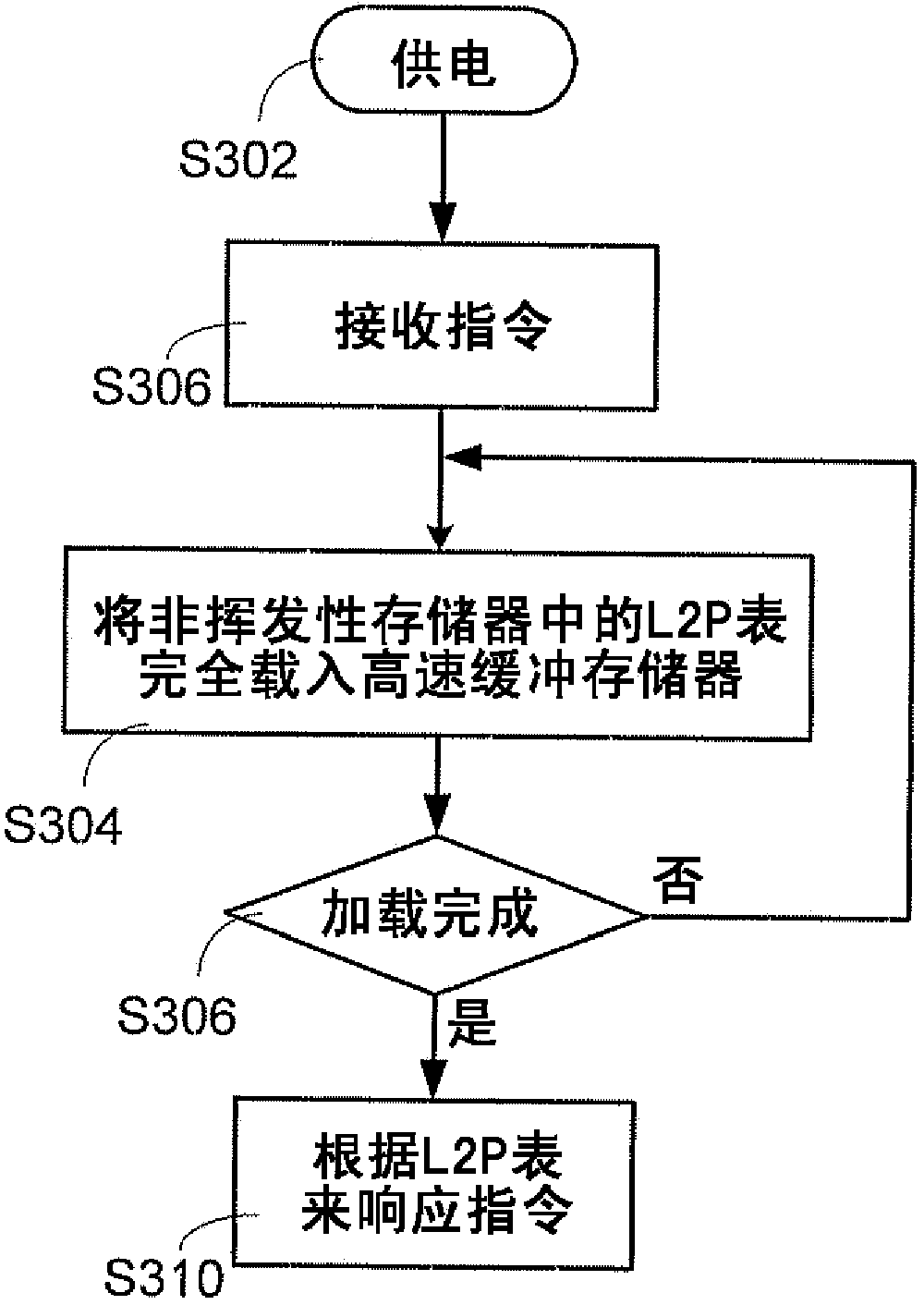
[0024] Since it takes a long time to load the complete L2P table to the cache memory when the existing solid state storage device is powered on, it takes a long time to respond to the command of the host. The present invention proposes a solid-state storage device and a method for establishing an L2P table thereof. When the solid-state storage device is powered on, it can quickly respond to a host computer's command to improve the access efficiency of the solid-state storage device.

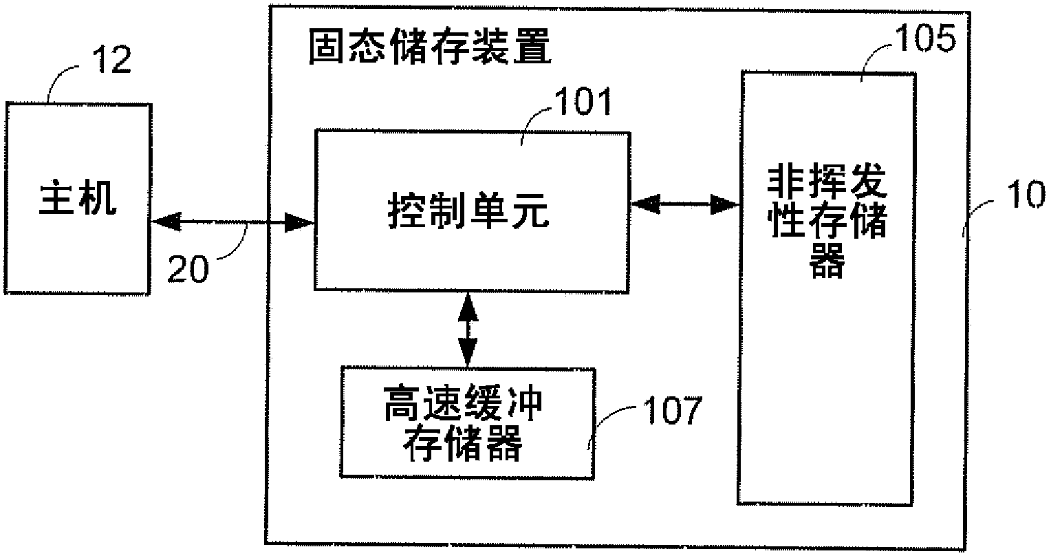
[0025] Since the main feature of the present invention is to improve the method for the control unit 101 to establish the L2P table, there is no change figure 1 Hardware architecture of solid-state storage devices. Therefore, the hardware architecture of the solid state storage device will not be described again.

[0026] According to the embodiment of the present invention, when the solid state storage device 10 is powered on, it can quickly load a part of the L2P table in response to the comma...


PUM


Abstract

The invention relates to a method for establishing an address mapping table of a solid-state memory. The method comprises the following steps of receiving a command sent by a host computer when the solid-state memory starts; computing a logic configuration address according to a logic block address accompanying with the command; establishing a mapping table of a first part, beginning from a start address in the mapping table, in a cache memory by utilizing the computed logic configuration address as the start address; responding to the command according to the mapping table of the first part.

Description

technical field [0001] The present invention relates to a method for establishing an address correspondence table of a solid-state storage device, and in particular to a solid-state storage device and a method for establishing a logic-to-physical address correspondence table (L2P Table) thereof. Background technique [0002] As is well known, a solid state storage device (Solid State Drive, SSD) uses a non-volatile memory (non-volatile memory) as a main storage element. That is to say, after the data is written into the non-volatile memory, once the system power is turned off, the data is still stored in the solid-state storage device. [0003] Please refer to figure 1 , which is a schematic diagram of a solid-state storage device. The solid state storage device 10 includes a control unit 101 , a cache memory (cache memory) 107 and a non-volatile memory 105 . Outside the solid state storage device 10 , the control unit 101 transmits commands and data to and from a host (h...

Claims


Application Information

Patent Timeline
Patent Type & Authority Applications(China)
IPC IPC(8): G06F12/08
CPCG06F12/08G06F12/0246
Inventor 刘其铠陈彦衡
Owner LITE ON TECH CORP
Why Eureka
Try Eureka