
Digital oscilloscope isolation channel circuit

A technology of digital oscilloscope and channel isolation, which is applied in the direction of digital variable display, etc. It can solve the problems of signal distortion, low accuracy, poor linearity and channel frequency response consistency, etc., and achieve large isolation bandwidth, high safety level and large dynamic range Effect

Inactive Publication Date: 2014-01-01
THE 41ST INST OF CHINA ELECTRONICS TECH GRP
View PDF5 Cites 6 Cited by
  • Summary
  • Abstract
  • Description
  • Claims
  • Application Information

AI Technical Summary

Problems solved by technology

[0004] The technology of photoelectric isolation using optocoupler can achieve electrical mutual insulation between the input and output, but due to the non-linearity and temperature variation of the photocoupler, when the analog signal is isolated, the signal will be greatly generated. Even if it is compensated by feedback and calibration techniques, it can only guarantee the linearity and accuracy of several MHz frequency signals. Therefore, digital oscilloscopes that use optocouplers to achieve signal isolation have a small bandwidth, generally several MHz, the accuracy of voltage measurement is low, and the linearity and frequency response consistency of channels are poor

Method used


Image

  • Digital oscilloscope isolation channel circuit
  • Digital oscilloscope isolation channel circuit
  • Digital oscilloscope isolation channel circuit

Examples


Embodiment Construction

[0029] Below in conjunction with accompanying drawing and specific embodiment the present invention is described in further detail:

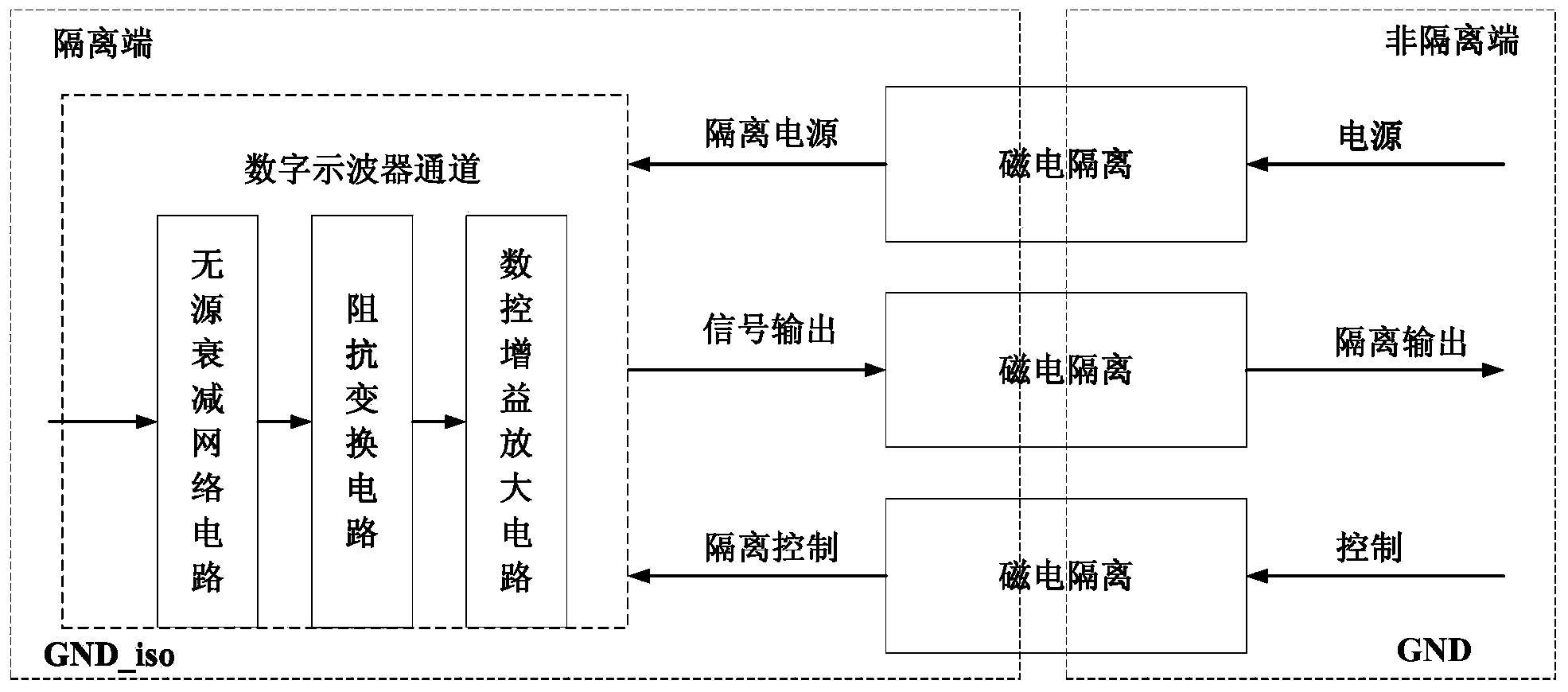
[0030] combine figure 2 As shown, a digital oscilloscope isolation channel circuit includes a passive attenuation network circuit, an impedance transformation circuit, a digitally controlled gain amplifier circuit, and an isolation circuit.

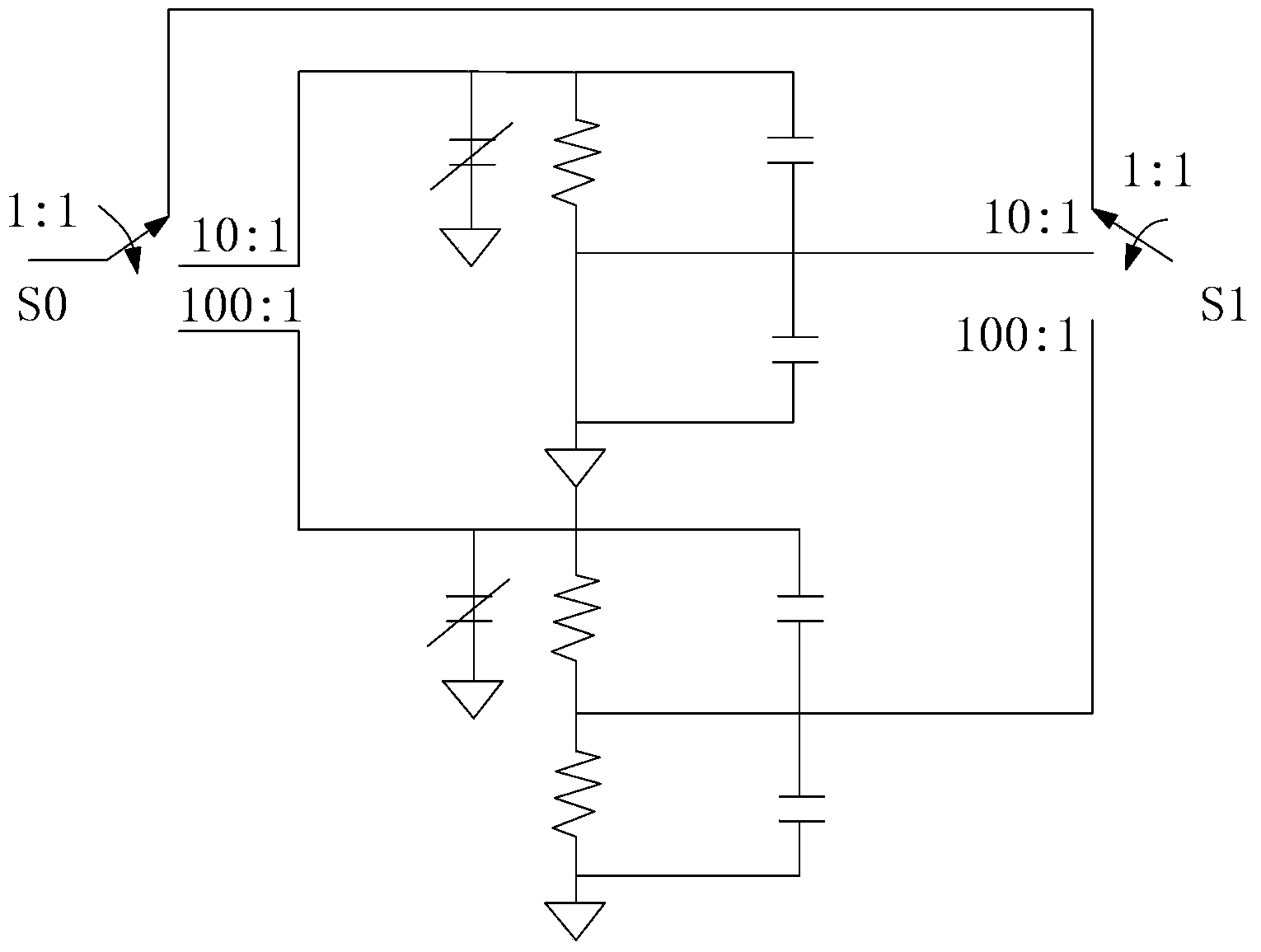
[0031] like image 3 As shown, the passive attenuation network circuit includes a magnetic latching relay, a voltage division compensation network of precision resistors and capacitors, which is used to attenuate high-power signals by 1:1, 10:1 or 100:1, and realize digital oscilloscope oscilloscope Table 200mV / div~100V / div vertical sensitivity range. image 3 Among them, S0 is the input end of the passive attenuation network circuit, that is, the input end of the digital oscilloscope channel, and S1 is the output end of the passive attenuation network circuit, which is connected to the input end of the ...


PUM


Abstract

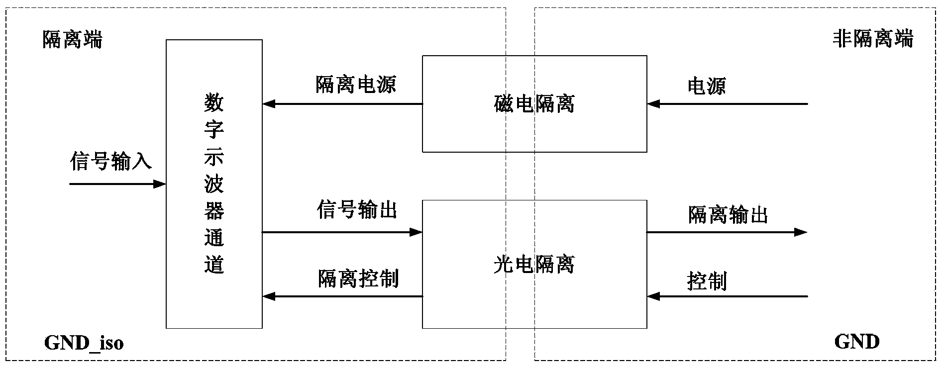
The invention belongs to the technical field of digital oscilloscopes, and particularly discloses a digital oscilloscope isolation channel circuit which comprises a passive attenuation network circuit, an impedance conversion circuit, a numerical control gain amplification circuit and an isolation circuit. The isolation circuit comprises a power isolation circuit, a digital isolation circuit and an analog signal isolation circuit, and the power isolation circuit, the digital isolation circuit and the analog signal isolation circuit are used for isolating a power supply from the ground, digital control signals and analog input signals respectively. A magneto-electricity isolation technology is adopted, the complete electrical isolation between the input end and the output end of a digital oscilloscope is achieved, and the isolation safety level reaches 1000V CATII. The measurement bandwidth ranges from DC to 200MHz, and smooth amplitude-frequency responses are maintained. The vertical sensitivity ranges from 2Mv / div to 100V / div. The digital oscilloscope isolation channel circuit has the advantages of being large in isolation bandwidth, high in floating isolating safety level, large in dynamic range, high in measurement precision, good in linearity and the like.

Description

technical field [0001] The invention belongs to the technical field of digital oscilloscopes, in particular to a digital oscilloscope isolation channel circuit. Background technique [0002] Signal isolation technology is to make the analog signal do not have a current connection across the barrier between the sending end and the receiving end when it is sent, allowing the difference between the ground potentials of the sending end and the receiving end to be as high as several thousand volts, which can prevent different grounds that may damage the signal. Loop current between potentials; at the same time, it can generate an isolation of unsafe signals for operators, improving the safety of digital oscilloscopes. However, most of the channels of domestic digital oscilloscopes use non-isolated design. Although the bandwidth is high, they are not isolated from the ground. When the analog signal is sent, there is a current connection through the barrier between the sending end ...

Claims


Application Information

Patent Timeline
Patent Type & Authority Applications(China)
IPC IPC(8): G01R13/02
Inventor 刘洪庆李云彬郭同华陈秋伟孙龙
Owner THE 41ST INST OF CHINA ELECTRONICS TECH GRP
Learn More