
Upper limb exoskeleton steering mechanism driven by pneumatic muscles

A technology of pneumatic muscles and power-assisted mechanisms, which is applied to manipulators, program-controlled manipulators, manufacturing tools, etc., can solve the problems of low power/mass, low system work efficiency, and high system cost, so as to improve lifting strength, improve machine capacity, good flexibility

Active Publication Date: 2013-12-25
ZHEJIANG UNIV
View PDF8 Cites 39 Cited by
  • Summary
  • Abstract
  • Description
  • Claims
  • Application Information

AI Technical Summary

Problems solved by technology

The disadvantage of motor drive is that the power / mass ratio is small, and the motor with limited weight is difficult to bear a large load
The disadvantages of hydraulic drive are mainly leakage problems, low system efficiency and high system cost
Although the pneumatic drive method has the advantages of being friendly to the environment and the human body, light components, and cheap prices, the power / volume-to-mass ratio of conventional air cylinder actuators is far inferior to that of hydraulic cylinders, so it cannot meet the needs of large customers. The need for exoskeleton booster systems with load requirements but limited installation space and high requirements for portability has not been widely used

Method used


Image

  • Upper limb exoskeleton steering mechanism driven by pneumatic muscles
  • Upper limb exoskeleton steering mechanism driven by pneumatic muscles
  • Upper limb exoskeleton steering mechanism driven by pneumatic muscles

Examples


Embodiment Construction

[0022] The present invention will be further described below in conjunction with drawings and embodiments.

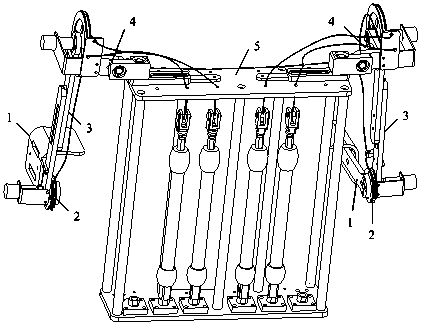
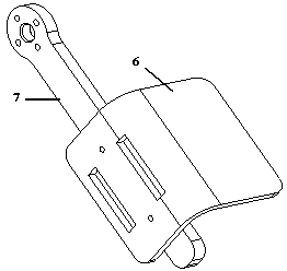
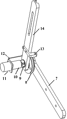
[0023] Such as figure 1 As shown, the present invention comprises two single-arm components and a back support 5 with the same structure; the single-arm components are sequentially composed of forearm 1, elbow joint 2, upper arm 3 and shoulder joint 4 from bottom to top, and in the two single-arm components Shoulder joint 4 is installed on the both sides of back support 5 top plates respectively, and two elbow joint shafts are connected with respective pneumatic muscles in back support 5 through respective elbow steel wire traction lines 36, and two shoulder joint shafts are respectively passed through respective shoulder joints. The steel wire pull line 37 of the part is connected with the respective pneumatic muscles in the back support 5. There are four degrees of freedom in the single-arm component, which are flexion-extension of the elbow, flexion-extension of the...


PUM


Abstract

The invention discloses an upper limb exoskeleton steering mechanism driven by pneumatic muscles. The upper limb exoskeleton steering mechanism driven by the pneumatic muscles comprises two single arm components and a back support; the two single arm components have the same structure; shoulder joints of the two single arm components are arranged on the bilateral sides of a back support top plate respectively; two elbow joint shafts are connected with the respective pneumatic muscles which are arranged in the back support through respective elbow steel wire traction lines; two shoulder joint shafts are connected with the respective pneumatic muscles which are arranged in the back support through respective shoulder steel wire traction lines; each single arm component has four degrees of freedom; the four degrees of freedom comprise elbow flexion and extension, flexion and extension of the shoulder joints, outreach and adduction of the shoulder joints and internal rotation and external rotation rotating pairs of the shoulder joints. After the upper limb exoskeleton steering mechanism driven by the pneumatic muscles is worn, the lift strength can be greatly improved when a wearer lifts heavy objects with the aid of tension caused by contraction of the pneumatic muscles and accordingly the purpose of improving the function strength of the wearer can be achieved. The upper limb exoskeleton steering mechanism driven by the pneumatic muscles is of great significance when the strength of people is not enough to support required loads in occasions of military operations, disaster relief and rescue and the like.

Description

technical field [0001] The invention relates to a robot with a bionic structure, in particular to an upper limb exoskeleton power-assisted mechanism driven by pneumatic muscles. Background technique [0002] Exoskeleton technology is a wearable robot technology, a new mechatronic device developed by imitating the exoskeleton in the biological world, which can be worn on the outside of the operator's body, providing the operator with protection, body support, sports assistance, etc. and other functions. [0003] Most exoskeletons are driven by motors or hydraulics, only a few are driven by pneumatics, and they are mainly used in light-load applications such as medical rehabilitation. The disadvantage of motor drive is that the power / mass ratio is small, and the motor with limited weight is difficult to bear a large load. The disadvantages of hydraulic drive are mainly leakage problems, low system efficiency and high system cost. Although the pneumatic drive method has the ...

Claims


Application Information

Patent Timeline
IPC IPC(8): B25J9/00B25J9/14
Inventor 刘昊张丹婷李智寿赵勇陶国良
Owner ZHEJIANG UNIV
Learn More