
Thermosetting cutting knife

A cutting knife and support tube technology, applied in the field of medical devices, can solve the problems of easy burnout of hot wires, small hinge size, scalding of intra-abdominal tissue, etc., and achieve the effects of preventing local resistance from increasing, stabilizing the holding force, and being convenient to operate.

Active Publication Date: 2013-12-18
ANHUI AOFO MEDICAL EQUIP TECH
View PDF6 Cites 0 Cited by
  • Summary
  • Abstract
  • Description
  • Claims
  • Application Information

AI Technical Summary

Problems solved by technology

[0006] The current thermal coagulation cutting knife, the mechanical transmission mechanism that controls the movement of its clamping claws is usually a combination of a link mechanism or a high-pair mechanism and a link mechanism; the current for heating is conducted through a hinge or a high-pair contact. Some potential risks and limitations. These devices have many inconveniences in use and manufacture. The disadvantages are mainly reflected in: the hinge is small in size and needs to be conductive. When the relative rotation of the clamping claw and the outer tube produces poor contact, the local resistance increases Large and hot, and even produce electric sparks, in severe cases, it will burn the intra-abdominal tissue during the operation; the two claws cannot produce a large clamping force; during the operation, the hot wire is in contact with the human tissue part in the length direction, and the contact part is cooled by the liquid. The temperature on the whole heating wire is uneven, the heating wire is easy to burn out, and may burn the intra-abdominal tissue during the operation; the heating wire is directly in contact with the coating, which increases the temperature rise of the coated plastic material. Insufficiency of the thermal coagulation cutting knife, the present invention provides a minimally invasive intelligent coagulation cutting knife that is easy to use, safe and reliable
After extensive searching, no ideal technical solution has been found

Method used


Image

  • Thermosetting cutting knife
  • Thermosetting cutting knife
  • Thermosetting cutting knife

Examples


Embodiment Construction

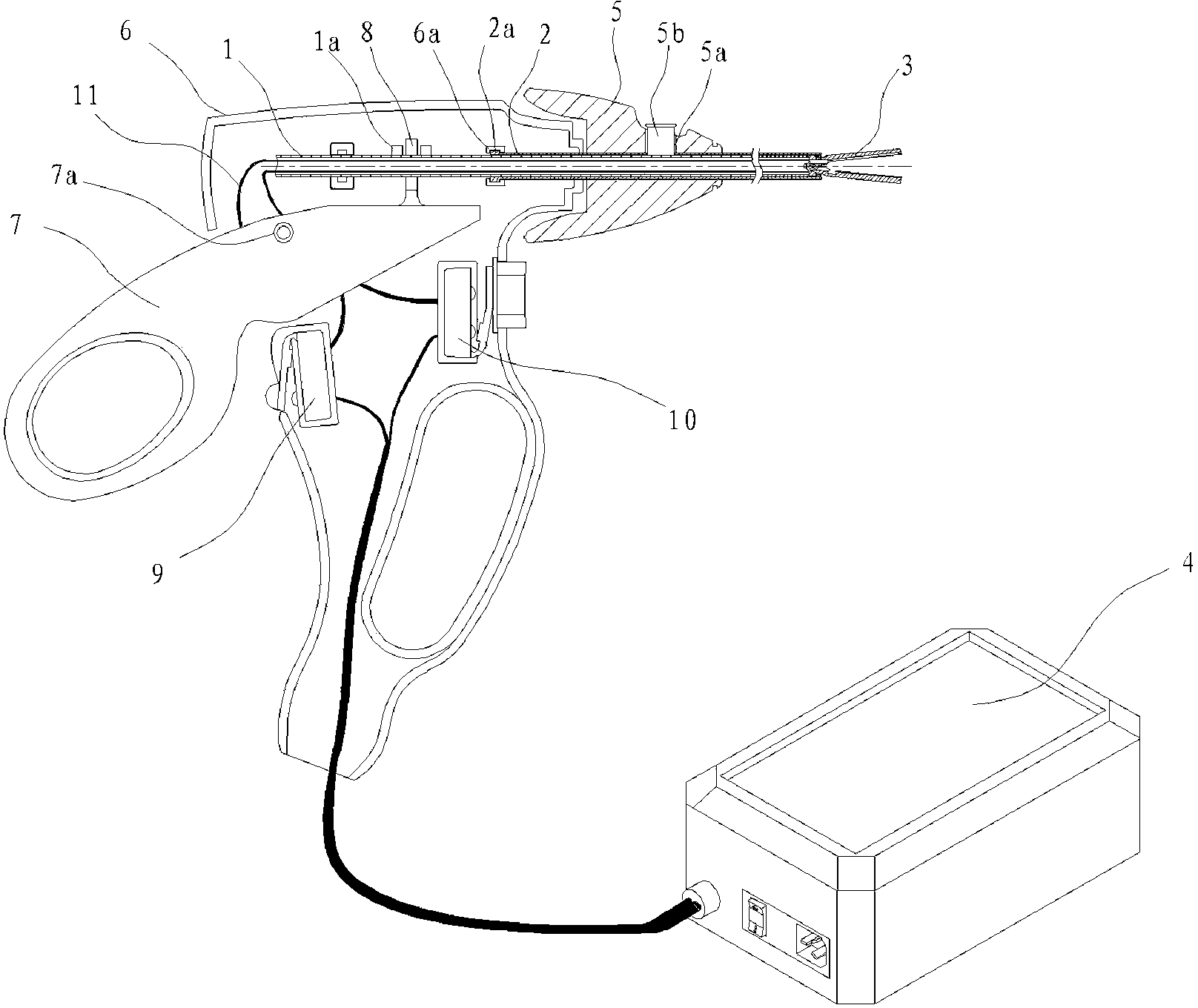
[0027] like figure 1 As shown, a thermocoagulation cutting knife provided by the present invention includes a casing 6, a wrench 7 is connected in the casing 6, the front end of the wrench 7 is connected to the support tube 1, and the front end of the support tube 1 is connected with the clamping claws 3 that cooperate with each other. , characterized by:

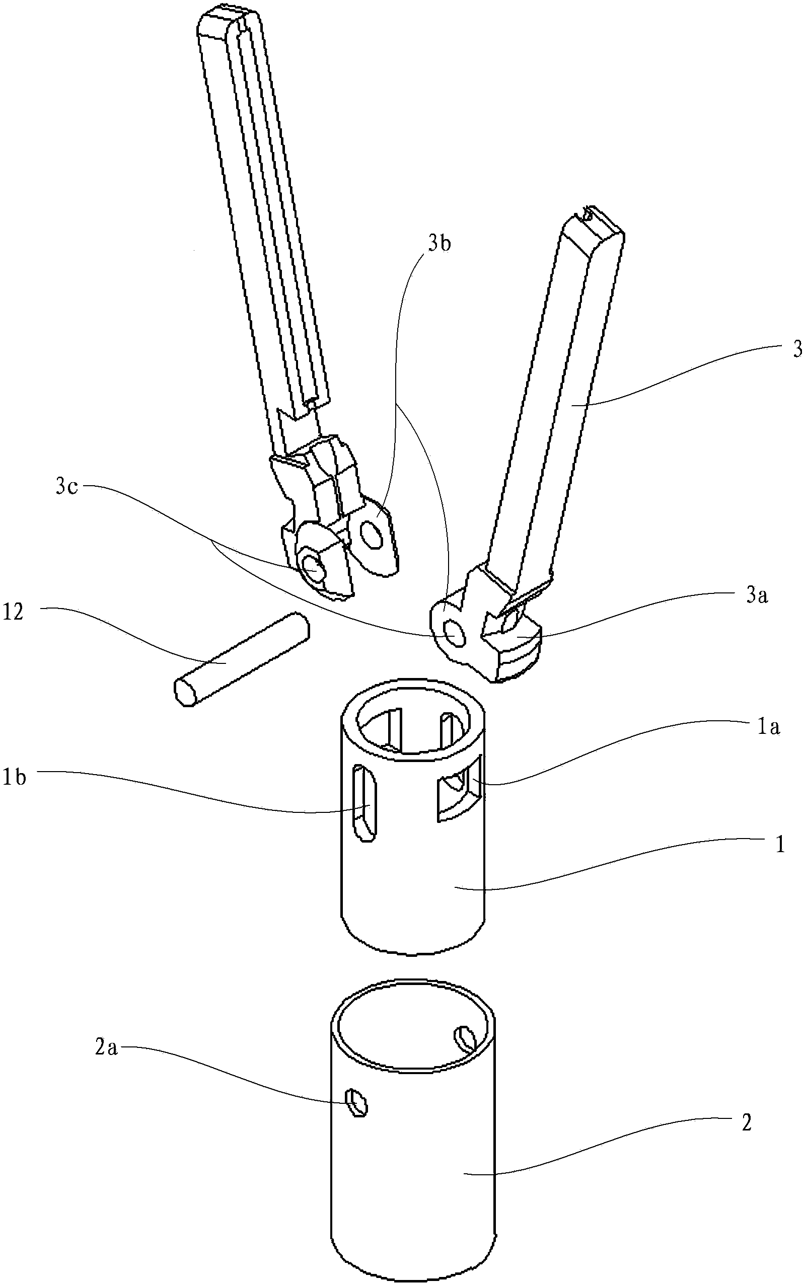
[0028] a. to combine figure 2 As shown, a section of outer tube 2 is sleeved on the support tube 1, and a flange 2a is provided at the rear end of the outer tube 2. There are two symmetrical square openings 1a, and two symmetrical rectangular chute 1b are also provided at the front end of the support tube 1, and the penetration lines of the two chute 1b and the penetration line of the overlapping opening 1a are perpendicular to each other , There are two symmetrical circular fixing holes 2a at the front end of the outer tube 2, each fixing hole 2a is matched with the corresponding chute 1b, and a square strap is arranged...


PUM


Abstract

The invention relates to a thermosetting cutting knife which comprises a housing (6), wherein both a wrench (7) and a supporting tube (1) are connected to the interior of the housing (6); the front end of the supporting tube (1) is matched and connected with gripper jaws (3) matched mutually; the thermosetting cutting knife is characterized in that the supporting tube (1) is sleeved with a section of outer tube (2); the supporting tube (1) and the outer tube (2) are connected with two gripper jaws (3) matched mutually; the wrench (7) is connected with the supporting tube (1) through a shift fork (8); the gripper jaws (3) are connected with an electronic control box (4) through guide lines (11). The thermosetting cutting knife has the advantages that the thermosetting cutting knife is convenient to operate, larger and stable clamping force can be provided for the gripper jaws, the guide lines are adopted for electric conduction, so that the phenomenon of partial electric resistance increase is eliminated, and meanwhile, the gripper jaws provided by the invention are heated uniformly.

Description

technical field [0001] The invention relates to a medical device, in particular to a thermocoagulation cutting knife for minimally invasive surgery. Background technique [0002] Minimally invasive surgery is performed using modern medical instruments such as laparoscopy and thoracoscopic surgery and related equipment. It has the advantages of less trauma, less pain, and faster recovery. With the development and progress of technology, minimally invasive surgery has penetrated into various fields of surgery. [0003] The thermal coagulation cutter is one of the most important instruments of the thermal welding technology system in minimally invasive surgery. Its principle is to simultaneously coagulate and seal soft tissues through heat and pressure. The heat is generated through resistance wires with the help of low-voltage direct current. Under the action of local high-efficiency heat energy, the protein chain of the protein in the clamping claw is opened, and the hinge s...

Claims


Application Information

Patent Timeline
IPC IPC(8): A61B18/08
Inventor 段和平叶兵胡毅汪进余海东苗长胜谢鸿年
Owner ANHUI AOFO MEDICAL EQUIP TECH
Learn More