Double apron drafting device in rear area of ring spinning frame
A technology of drafting device and spinning frame, which is applied in the field of double apron drafting device in the rear area of ring spinning frame, which can solve problems such as small spinning range, excessive coarse and fine details, torsional vibration of rear roller, etc., and achieve strong control, Fewer coarse details and better yarn evenness
- Summary
- Abstract
- Description
- Claims
- Application Information
AI Technical Summary
Problems solved by technology
Method used
Image
Examples
Embodiment 1
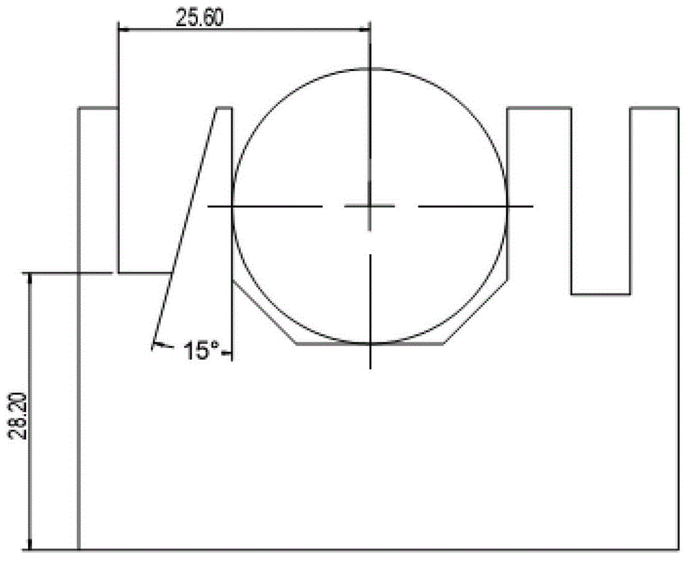
[0018] Such as figure 1 , image 3 and Figure 5 As shown, the double-apron drafting device in the rear area of the ring spinning machine in this embodiment includes a wedge-groove type rear roller slide 1, a wedge-shaped positioning block 2, a fastening screw 3, a lower short apron 4, and a small partition The lower pin 5 from the special-shaped section, the lower apron block 6, the rear paw presser connecting block 7, the cradle 12 and the general upper pin 13, wherein: it also includes the upper short apron 14, the rear top roller 15, and the rear roller 16. Rear roller bearing 17, traversing flat iron 18, roller stool 19 and roving feeding horn 20; the wedge-shaped groove of the wedge-groove type rear roller slide seat 1 is installed with a small-distance special-shaped cross-section lower pin 5 and a wedge-shaped positioning block 2 And fixed by the fastening screw 3, the lower pin 5 of the special-shaped section with a small distance is equipped with a dovetail-shape...
Embodiment 2
[0020] Such as figure 2 , Figure 4 and Figure 5 As shown, the double apron drafting device in the rear area of the ring spinning machine in another embodiment of the present invention includes a straight-groove rear roller slide 1', a small-gauge special-shaped cross-section lower pin 5, and a rear claw presser. Connecting block 7, SF type rolling tension frame assembly 8, tension frame supporting shaft 9, tension frame support block 10, lower long apron 11, cradle 12 and general upper pin 13, wherein: it also includes upper short apron 14, Rear top roller 15, rear roller 16, rear roller bearing 17, traverse flat iron 18, roller stool 19 and roving feeding horn 20; tension frame support block 10 is installed on the roller stool 19 and is connected with tension frame support shaft 9, SF The type rolling tension frame assembly 8 is matched with the tension frame support shaft 9, and the lower long apron 11 is set on the rear roller 16, the small-gauge special-shaped secti...
PUM
 Abstract
Description
Claims
Application Information
 - R&D
- Intellectual Property
- Life Sciences
- Materials
- Tech Scout
- Unparalleled Data Quality
- Higher Quality Content
- 60% Fewer Hallucinations
Browse by: Latest US Patents, China's latest patents, Technical Efficacy Thesaurus, Application Domain, Technology Topic, Popular Technical Reports.
© 2025 PatSnap. All rights reserved.Legal|Privacy policy|Modern Slavery Act Transparency Statement|Sitemap|About US| Contact US: help@patsnap.com


