
Moving contact insertion travel detecting device of high-voltage isolating switch

A high-voltage isolation switch, stroke detection technology, applied in switchgear, electrical components, etc., can solve the problems of insufficiency of moving contacts, inaccurate placement of moving contacts, damage to high-voltage isolation switches, etc., and achieve accurate insertion stroke. control effect

Active Publication Date: 2013-11-27
STATE GRID CORP OF CHINA +1
View PDF3 Cites 4 Cited by
  • Summary
  • Abstract
  • Description
  • Claims
  • Application Information

AI Technical Summary

Problems solved by technology

The structure of the plug-in high-voltage isolating switch mainly includes moving contacts, static contacts and insulators. The opening and closing of the high-voltage isolating switch is realized by driving the moving contacts. It is very important. If the insertion position of the moving contact is not enough, there will be a gap between the moving contact and the static contact when the switch is closed. At this time, an arc will be generated between the moving contact and the static contact, which will damage the high voltage isolation. switch, even causing safety accidents
In the prior art, when inspecting the high-voltage isolating switch, there is no special tool for checking the insertion stroke of the moving contact. The setting position of the moving contact is realized by the maintenance personnel tapping the conductive rod connected to the moving contact. Inaccurate enough, it is prone to the problem that the setting of the moving contact is not in place

Method used


Image

  • Moving contact insertion travel detecting device of high-voltage isolating switch

Examples


Embodiment Construction

[0010] The present invention will be further described below in conjunction with the accompanying drawings and embodiments.

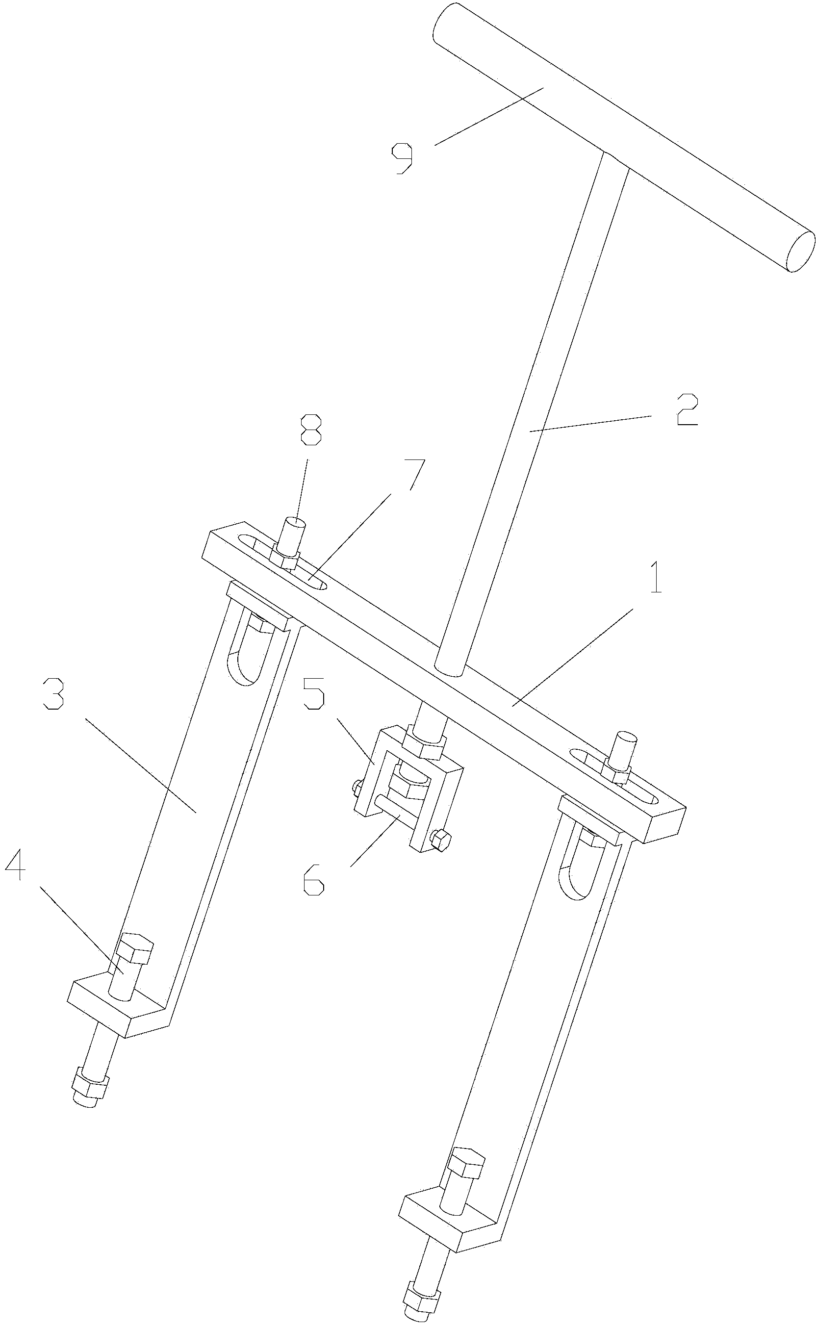
[0011] As shown in the figure, the high-voltage isolating switch moving contact insertion stroke detection device of this embodiment includes a cross bar 1, a push rod 2 and a pull plate 3. The push rod 2 is vertically installed in the middle of the cross bar 1 and connected to the cross bar The rod 1 is threaded, and the pull plates 3 are two pieces. The two pull plates 3 are arranged at the two ends of the cross bar 1, and the two pull plates 3 are symmetrically arranged relative to the push rod 2. The ends of the two pull plates 3 are also A first bolt 4 parallel to the push rod 2 is provided; the end of the push rod 2 is connected with a U-shaped block 5 that is rotatably matched with the push rod 2, and the U-shaped block 5 is detachably connected with a crossing The connecting rod 6 of U-shaped block opening.

[0012] When overhauling the high-vo...


PUM


Abstract

The invention discloses a moving contact insertion travel detecting device of a high-voltage isolating switch. The device comprises a transverse rod, a push rod and pull plates. The push rod vertically penetrates through the middle portion of the transverse rod and is in threaded connection with the transverse rod, the pull plates are two in number, the two pull plates are arranged at the two ends of the transverse rod and are symmetrically arranged relative to the push rod, and the end portion of each pull plate is further provided with a first bolt parallel with the push rod. The end portion of the push rod is connected with a U-shaped block matched with the push rod in a rotary mode, and the U-shaped block is detachably connected with a connecting rod which transversely penetrates through the opening of the U-shaped block. The first bolts and the end portion of the high-voltage isolating switch are connected through flanges, the connecting rod on the U-shaped block is connected with a conductive rod which is arranged in the high-voltage isolating switch and connected with a moving contact, and the moving contact can be pushed to move when the push rod is rotated. Besides, the moving length of the push rod can be measured to obtain the insertion travel length of the moving contact. Therefore, the insertion travel of the moving contact can be controlled precisely, the fact that the moving contact is accurately arranged in guaranteed, and the discharging phenomenon in the work process does not occur.

Description

technical field [0001] The invention relates to a tooling, in particular to a device for detecting the insertion stroke of a moving contact of a high-voltage isolating switch. Background technique [0002] The high-voltage isolating switch plays the role of isolating voltage to ensure the safety of high-voltage electrical appliances and devices during maintenance work. The structure of the plug-in high-voltage isolating switch mainly includes moving contacts, static contacts and insulators. The opening and closing of the high-voltage isolating switch is realized by driving the moving contacts. It is very important. If the insertion position of the moving contact is not enough, there will be a gap between the moving contact and the static contact when the switch is closed. At this time, an arc will be generated between the moving contact and the static contact, which will damage the high voltage isolation. switch, and even cause safety accidents. In the prior art, when insp...

Claims


Application Information

Patent Timeline
Patent Type & Authority Applications(China)
IPC IPC(8): H02B3/00
Inventor 邓旭东魏钢段永超汪力肖敏任昌智
Owner STATE GRID CORP OF CHINA
Learn More