Method for measuring distribution of intensity of light spots of reflecting type concentrating photovoltaic condenser

A concentrating photovoltaic and intensity distribution technology, which is applied in the direction of testing optical properties, can solve problems such as high energy flow density, and achieve the effect of simple operation and easy operation

Active Publication Date: 2013-11-27
兰州大成科技股份有限公司 +1
View PDF7 Cites 4 Cited by
  • Summary
  • Abstract
  • Description
  • Claims
  • Application Information

AI Technical Summary

Benefits of technology

This technology allows us to easily determine if there's an ideal amount of sunlight that produces good power from solar panels by accurately detecting evenly distributed brightness across them.

Problems solved by technology

This patented technical problem addressed in this patents relates to improving the quality and quantity of highly efficient concentrations of solar electric generators due to increasingly larger sizes required while also reducing costs associated with fabrication. Current techniques involve complex processing steps involving multiple components like laser diodes, dichroics filters, and other materials, making them difficult to control accurately during mass producing.

Method used


Image

  • Method for measuring distribution of intensity of light spots of reflecting type concentrating photovoltaic condenser
  • Method for measuring distribution of intensity of light spots of reflecting type concentrating photovoltaic condenser
  • Method for measuring distribution of intensity of light spots of reflecting type concentrating photovoltaic condenser

Examples


Embodiment

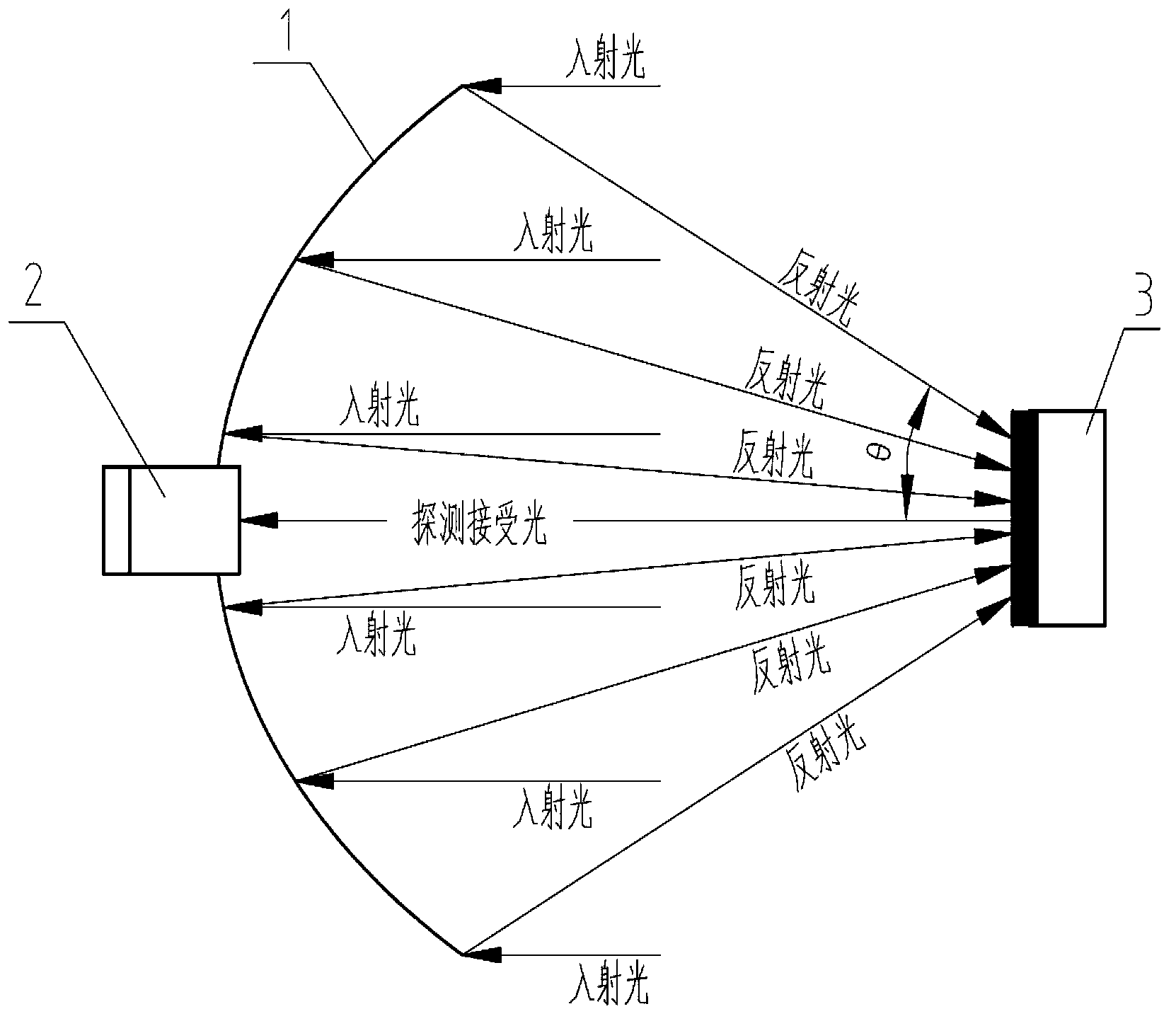
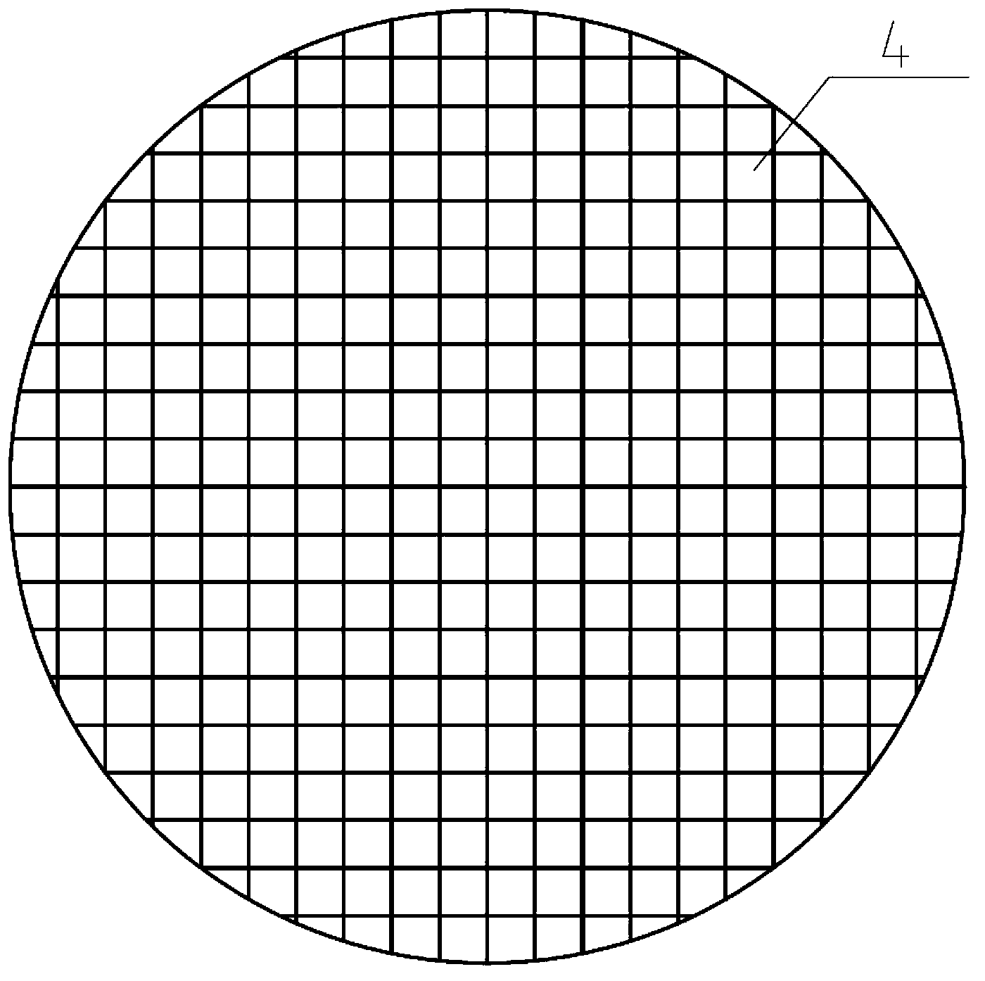
[0027] Example: see figure 1 2. A method for measuring the intensity distribution of light spot of a reflective concentrating photovoltaic concentrator, characterized by comprising the following steps: (1) dividing the rotating parabolic reflective surface into reflective elements of a certain area; (2) using a detector to record the solar radiation After each reflection element is reflected, the image formed on the reflection plate is a pixel; (3) each pixel is superimposed to obtain the light intensity distribution on the reflection plate of the reflective concentrator.

[0028] The area of ​​the reflecting element needs to be smaller than the area of ​​the reflecting plate.

[0029] The detector is fixed at the lowest point of the rotating parabolic reflecting surface when recording the picture elements on the reflector after the sunlight is reflected by each reflecting element. The detector is fixed to the vertex of the rotating paraboloid, that is, the lowest point, and ...

experiment example

[0038] Experimental example: see figure 1 , a method for measuring the spot intensity distribution of a reflective concentrating photovoltaic concentrator,

[0039] The opening section of the condenser of the rotating parabolic mirror 1 is a circle with a diameter of 3.2 m.

[0040] The detector 2 is a commercially available digital camera. It is installed at the lowest point of the rotating parabolic reflector, that is, at the apex of the parabola of the largest cross-section.

[0041] The reflector 3 is an ordinary plane reflector, the size of the mirror surface is 200mm×200mm, and the reflectivity of the mirror surface is 93%.

[0042] The reflection plate 3 is 2.77 m away from the opening section of the rotating parabolic mirror 1 .

[0043] The measurement of the light intensity distribution on the reflector 3 after the sunlight is reflected by the rotating parabolic reflector 1 is carried out according to the following steps:

[0044] (1) Divide the rotating paraboli...


PUM


Abstract

The invention relates to reflecting type concentrating photovoltaics, in particular to a method for measuring the distribution of the intensity of light spots of a reflecting type concentrating photovoltaic condenser. The method for measuring the distribution of the intensity of the light spots of the reflecting type concentrating photovoltaic condenser is characterized by including the following steps that a rotating parabolic reflecting surface is divided into reflecting elements with a certain area; a detector is utilized to record imaging of sunlight on a reflecting plate after the sunlight is reflected by the reflecting elements, and the imaging is used as image elements; the image elements are stacked to obtain the distribution of the light intensity on the reflecting plate of the reflecting type condenser. The method has the advantages that a method which is simple and convenient to operate and used for measuring the uniformity of the light spots is provided for the high-power reflecting type concentrating photovoltaics, so that it is possible to measure the uniformity of the light spots which are high in energy current density and to measure the spacial distribution of the light intensity of the light spots which are high in energy current intensity.

Description


Claims


Application Information

Patent Timeline
Owner 兰州大成科技股份有限公司
Why Eureka
Try Eureka