A frame structure of a car-carrying disc lifting device

A technology of lifting device and car-carrying tray, which is applied in the direction of buildings, building types, buildings, etc. where cars are parked, and can solve the problem of unfavorable overall rigidity and geometric accuracy of the lifting frame body, difficult control of geometric dimensions and shape and position tolerances, and affecting lifting loads. To improve product quality and operational stability, overcome static and dynamic geometric deformation, and improve the accuracy of overall geometric dimensions and shape and position tolerances

Active Publication Date: 2015-08-05
NINGBO BANGDA INTELLIGENT PARKING SYST
View PDF8 Cites 0 Cited by
  • Summary
  • Abstract
  • Description
  • Claims
  • Application Information

AI Technical Summary

Problems solved by technology

However, there are certain defects in the vehicle-carrying disc lifting frame body of the above-mentioned patent: firstly, the left box frame, the middle box frame and the right box frame in the above-mentioned patent are casting structures, and its own weight is relatively large, and because the box in the above-mentioned patent The frame structure is a thin-walled box-frame casting, which has certain casting defects that are difficult to overcome, and its geometric dimensions and shape and position tolerances are also difficult to control; secondly, the top frame and bottom frame in the above-mentioned patents are split structures. This structure will adversely affect the overall rigidity and geometric accuracy of the lifting frame body, which in turn will affect the running quality of the lifting vehicle tray

Method used


Image

  • A frame structure of a car-carrying disc lifting device
  • A frame structure of a car-carrying disc lifting device

Examples


Embodiment Construction

[0017] The present invention will be further described in detail below in conjunction with the accompanying drawings.

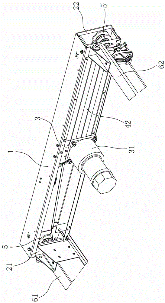
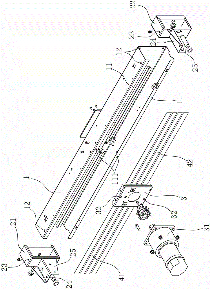
[0018] Such as Figure 1 ~ Figure 2 As shown, this embodiment discloses a frame structure of a vehicle-carrying disc lifting device, the frame structure includes a main beam 1 and a left box frame 21 and a right box frame 22 arranged on both sides of the main beam 1 .

[0019] Wherein, the main girder 1 is an integral part formed by bending and forming a steel plate. The cross section of the main girder 1 is U-shaped. The lifting mechanism (not shown in the figure), the main beam 1 is vertically bent and formed on the edge of the U-shaped opening to form opposite flanges 11, the flanges 11 are provided with mounting holes 111, and the mounting plate 3 is provided with There is a through hole 32 corresponding to the mounting hole 111, and the mounting plate 3 is fixedly arranged on the main beam 1 through a fastener (such as a screw, a bolt, or a pin shaft, e...


PUM


Abstract

A frame body structure of a car loading disc lifting device comprises a main beam, a left box frame and a right box frame, wherein the left box frame and the right box frame are arranged on the two sides of the main beam. The frame body structure is characterized in that the main beam is an integrated piece with the U-shaped cross section, the left box frame and the right box frame are respectively provided with a set of connecting face plates on the side face which is located on the same side as a U-shaped opening of the main beam, each set of connecting face plates comprise a first connecting face plate and a second connecting face plate, the first connecting face plates can be connected with the horizontal side face of a left side beam of a car loading disc and the horizontal side face of a right side beam of the car loading disc in an attaching mode, and the second connecting face plates can be connected with the perpendicular side face of the left side beam of the car loading disc and the perpendicular side face of the right side beam of the car loading disc in the attaching mode. The main beam is of a U-shaped structure which is integrally formed by a top support and a bottom support, so that the overall rigidity and assembly accuracy of the lifting frame body are greatly improved. The left box frame and the right box frame are of a frame type structure formed by welding thin steel plates, therefore, self weight is reduced, the geometric dimension and the form and location tolerance are easy to control, and accuracy of the overall geometric dimension and the form and location tolerance of the lifting frame body is remarkably improved.

Description

technical field [0001] The invention relates to a car-carrying disc structure of a three-dimensional garage, in particular to a frame structure of a car-carrying disc lifting device. Background technique [0002] At present, the three-dimensional garage that adopts the mechanical lifting and traversing method generally includes a front column, a front beam connecting the front column, a rear column, a rear beam connecting the rear column, and a longitudinal beam vertically connecting the front column and the rear column. , front beams, rear columns, rear beams and longitudinal beams together form a frame structure. The frame of this three-dimensional garage is usually provided with more than two layers of lift-type car-carrying tray and traversing-type car-carrying tray. The lift-type car-carrying tray is located on the lateral-moving car-carrying tray, and can only move vertically up and down along the frame of the three-dimensional garage under the control of the lifting ...

Claims


Application Information

Patent Timeline
Patent Type & Authority Patents(China)
IPC IPC(8): E04H6/18E04H6/06
Inventor 朱建华
Owner NINGBO BANGDA INTELLIGENT PARKING SYST
Why Eureka
Try Eureka