
Conductive connecting body structure of connector

A conductive connection and connector technology, applied in the field of conductive connector structure, can solve the problems of insufficient clamping force, high manufacturing cost, copper wire falling off, etc., and achieve stable clamping force, low implementation cost, simple, reasonable and compact structure. Effect

Active Publication Date: 2013-11-20
JIANGMEN KREALUX ELECTRICAL APPLIANCES
View PDF6 Cites 3 Cited by
  • Summary
  • Abstract
  • Description
  • Claims
  • Application Information

AI Technical Summary

Problems solved by technology

[0002] As an important connecting part in the electrical connection, the connector can be applied to single-strand, multi-strand, thin multi-strand copper wires, etc. In order to realize the connection of the wires on the connector, a push-type wire connector has appeared in the prior art. It includes a shell of plastic parts and a conductive connecting body located in the shell. The conductive connecting body is used to clamp the copper wire. The shell is provided with a pressing part, and the pressing part is provided with a pressing block. Drive the pressing block to squeeze out the clamping of the conductive connector to the copper wire, so as to abandon the traditional way of using bolts, rivets and other structures to compress the wire, which is convenient for wiring and unplugging. The clamping force of the wire is not enough, it is easy to make the copper wire fall off the connector without paying attention, and the structure is complicated, and the manufacturing cost is relatively high. Therefore, the traditional conductive connector needs to be further improved and upgraded

Method used


Image

  • Conductive connecting body structure of connector
  • Conductive connecting body structure of connector
  • Conductive connecting body structure of connector

Examples


Embodiment Construction

[0025] The present invention will be described in further detail below in conjunction with the accompanying drawings and embodiments.

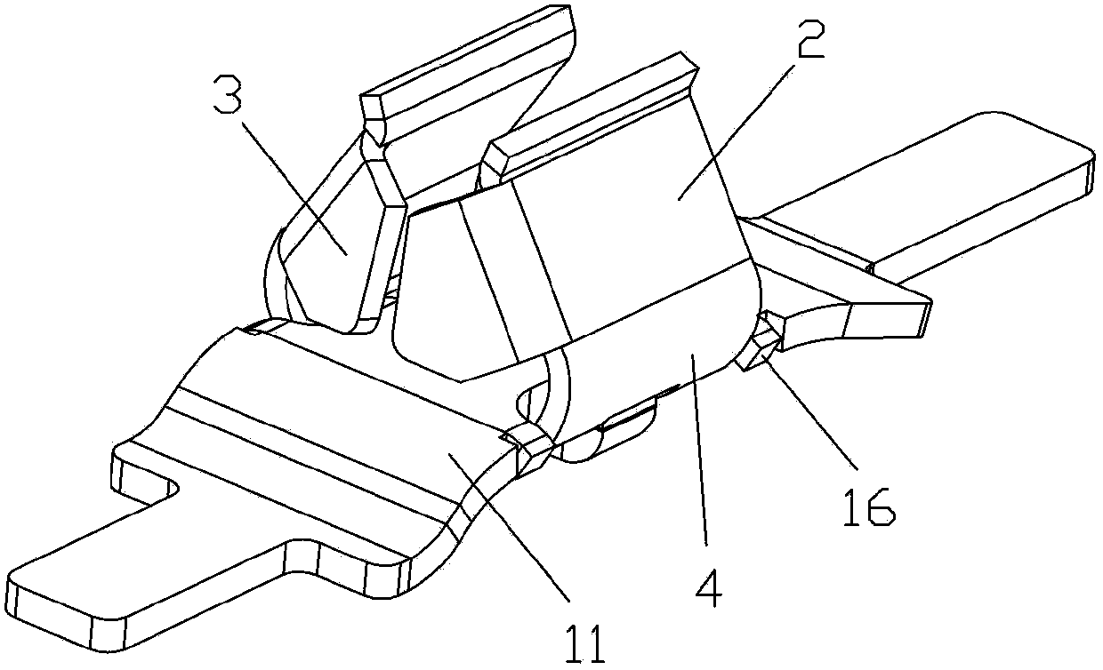
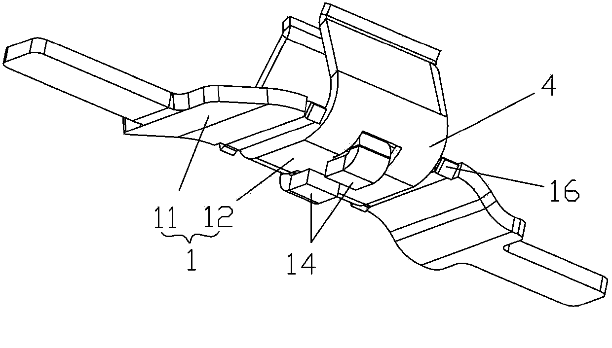
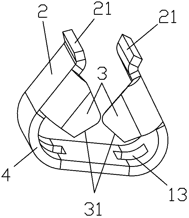
[0026] refer to Figure 1~Figure 11 , the conductive connector structure of the connector of the present invention includes a connecting body 1, and elastic clamping edges 2 are provided on opposite sides of the connecting body 1, and the elastic clamping edges 2 can be integrally formed on the connecting body 1, and the two The above-mentioned elastic clamping sides 2 are configured in a way that moves upward and closer together, so that the pressure block 53 on the connector housing 5 can easily push back the two elastic clamping sides 2, and the elastic clamping sides 2 can produce sufficient elastic reset after being pushed apart force, the elastic clip edge 2 is provided with a block 3, the block 3 can be integrally formed or welded on the elastic clip edge 2, the block 3 is provided with a bevel 31 or a gap 32 for clamping the wire 6, th...


PUM


Abstract

The invention discloses a conductive connecting body structure of a connector. The conductive connecting body structure of the connector comprises a connecting body. Two opposite side edges of the connecting body are respectively provided with an elastic clamping edge; the two elastic clamping edges are configured in a manner that the two elastic clamping edges are closer as the two elastic clamping edges goes up; each elastic clamping edge is provided with a fixture block; each fixture block is provided with a bevel connection or a notch used for clamping leads; the two elastic clamping edges are strutted; the leads can pass through below the bevel connections or the notches; the two elastic clamping edges are reset; the leads are clamped by the bevel connections or the notches of the fixture blocks, and therefore, the direct insertion and direct stripping of lead disassembly and assembly are realized while a manner adopted all the time that the leads are compressed by adopting structures, such as bolts, rivets and the like is abandoned; after the leads are clamped by the bevel connections or the notches of the fixture blocks, the leads are not easy to loose and fall under the unwariness condition; the clamping forces of the fixture blocks to the leads are stable. Moreover, the conductive connecting body structure of the connector disclosed by the invention is simple, reasonable and compact in structure, simple to operate and low in implementation cost.

Description

technical field [0001] The invention relates to a connector, in particular to a conductive connecting body structure of the connector. Background technique [0002] As an important connecting part in the electrical connection, the connector can be applied to single-strand, multi-strand, thin multi-strand copper wires, etc. In order to realize the connection of the wires on the connector, a push-type wire connector has appeared in the prior art. It includes a shell of plastic parts and a conductive connecting body located in the shell. The conductive connecting body is used to clamp the copper wire. The shell is provided with a pressing part, and the pressing part is provided with a pressing block. Drive the pressing block to squeeze out the clamping of the conductive connector to the copper wire, so as to abandon the traditional way of using bolts, rivets and other structures to compress the wire, which is convenient for wiring and unplugging. The clamping force of the wire...

Claims


Application Information

Patent Timeline
Patent Type & Authority Applications(China)
IPC IPC(8): H01R13/639
Inventor 饶小坡尹波青
Owner JIANGMEN KREALUX ELECTRICAL APPLIANCES
Learn More