
Wind tunnel testing system for annular rail models, vehicle models and bridge models

A bridge model and circular track technology, applied in the bridge model wind tunnel test system, circular track, and vehicle fields, can solve the problems of increasing the error of the test results, and the test results are far from the actual situation, and achieve the effect of improving the accuracy.

Inactive Publication Date: 2013-11-20
CENT SOUTH UNIV +1
View PDF7 Cites 17 Cited by
  • Summary
  • Abstract
  • Description
  • Claims
  • Application Information

AI Technical Summary

Problems solved by technology

In the actual situation, the train is in the aerodynamic flow around the bridge, and the operation of the train will inevitably affect the aerodynamic performance of the bridge. Similarly, the bridge is also in the aerodynamic flow around the train, and the bridge will inevitably affect the aerodynamic performance of the train. However, the existing test The devices ignore these effects, which makes the test results far from the actual situation and increases the error of the test results

Method used


Image

  • Wind tunnel testing system for annular rail models, vehicle models and bridge models
  • Wind tunnel testing system for annular rail models, vehicle models and bridge models
  • Wind tunnel testing system for annular rail models, vehicle models and bridge models

Examples


Embodiment Construction

[0048] It should be understood that the specific embodiments described here are only used to explain the present invention, not to limit the present invention.

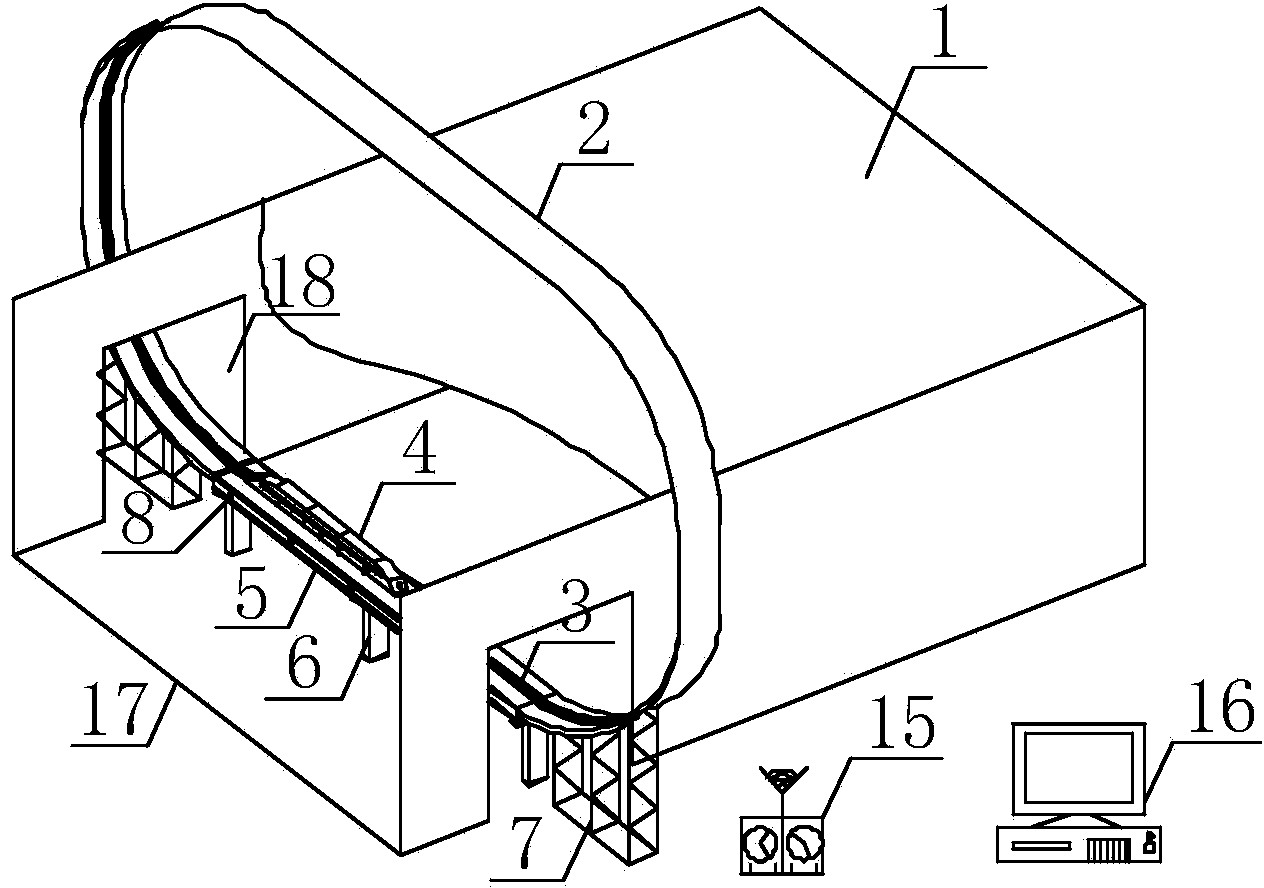
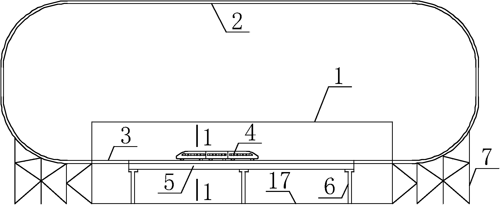
[0049] figure 1 It is a structural schematic diagram of a vertical single-line circular track, a vehicle, and a bridge model wind tunnel test system in an embodiment of the present invention; figure 2 Yes figure 1 The front view of the wind tunnel test system for vertical single-track circular track, train, and bridge models; image 3 It is a structural schematic diagram of a vertical double-line circular track, a train, and a bridge model wind tunnel test system according to an embodiment of the present invention; Figure 4 Yes image 3 The front view of the wind tunnel test system of the vertical double-track circular track, train and bridge model; Figure 5 Yes figure 2 Middle 1-1 section view; Image 6 Yes Figure 4 Middle 2-2 section view; Figure 7 It is a structural schematic diagram of a horizontal s...


PUM


Abstract

A wind tunnel testing system for annular rail models, vehicle models and bridge models includes a wind tunnel model test box (1) provided with at least one opening, wherein the space between opposite vertical side walls in one group on the wind tunnel model test box (1) is a wind tunnel testing zone; two opposite holes (18) are formed in the opposite vertical side walls in one group; a bridge model (5) is arranged between the two opposite holes (18); a rail is arranged on the bridge model (5); a vehicle model (4) for test is movably connected onto a rail (2); the rail (2) includes a guiding section rail (2) and a testing section rail (3); the guiding section rail (2) and the testing section rail (3) are connected from end to end to form an annular rail provided with an annular loop; the annular rail penetrates the two holes (18) simultaneously, or the annular rail simultaneously passes by the two holes (18) and the outer part of the wind tunnel model test box (1). According to the invention, the vehicle model can run on the rail in a cyclic manner, and the testing data obtained through testing more conforms to the actual condition.

Description

technical field [0001] The invention relates to the technical field of testing the aerodynamic characteristics of mobile trains, in particular to a wind tunnel test system for ring track, vehicle and bridge models. Background technique [0002] When high-speed railways cross special terrains such as rivers, lakes, mountains and canyons, they will inevitably face severe strong crosswinds. There have been too many train derailment accidents caused by strong crosswinds at home and abroad, so that the stability of train operation under strong crosswinds has received extensive attention. In order to ensure the safe operation of vehicles under strong crosswind, it is necessary to study the aerodynamic state of vehicles and bridges. The vehicle models in the existing vehicle model wind tunnel test devices are all static. The test system first only conducts coupling tests on the bridge or a single object of the stationary vehicle, without considering the mutual aerodynamic effect b...

Claims


Application Information

Patent Timeline
IPC IPC(8): G01M9/00G01M9/08
Inventor 朱志辉
Owner CENT SOUTH UNIV
Learn More