A mechanical inner core-pulling mold

An internal core-pulling and mechanical technology, applied in the field of mechanical core-pulling molds, can solve problems such as difficulty in removing hydraulic oil, poor aluminum plating, and easy splashing.

Active Publication Date: 2015-08-26
KUSN TUOAN PLASTIC PRODS
View PDF5 Cites 0 Cited by
  • Summary
  • Abstract
  • Description
  • Claims
  • Application Information

AI Technical Summary

Problems solved by technology

[0002] There are ribs and undercut slopes in the undercut area of ​​injection molded parts (such as figure 1 For the injection molded parts shown in ), an internal core-pulling mechanism is required on the mold to solve the problem of product ejection. In the prior art, the core-pulling generally uses an oil cylinder as the power, but if the core-pulling cylinder is used, the mold will be disassembled and repaired. The hydraulic oil in the oil cylinder is easy to splash onto the molding area of ​​the mold core. Since the product needs to be aluminum-plated after molding, the surface of the mold core forming area is polished to a mirror surface, so it is difficult to remove the hydraulic oil. Once there is hydraulic oil remaining on the surface of the molding area, it will cause Poor aluminum plating
Therefore, the mold does not allow the use of cylinder core pulling

Method used


Image

  • A mechanical inner core-pulling mold
  • A mechanical inner core-pulling mold
  • A mechanical inner core-pulling mold

Examples


Embodiment Construction

[0015] Below in conjunction with specific embodiment, further illustrate the present invention. It should be understood that these examples are only used to illustrate the present invention and are not intended to limit the scope of the present invention. In addition, it should be understood that after reading the content taught by the present invention, those skilled in the art may make various changes or modifications to the present invention, and these equivalent forms also fall within the scope defined by the appended claims of the present application.

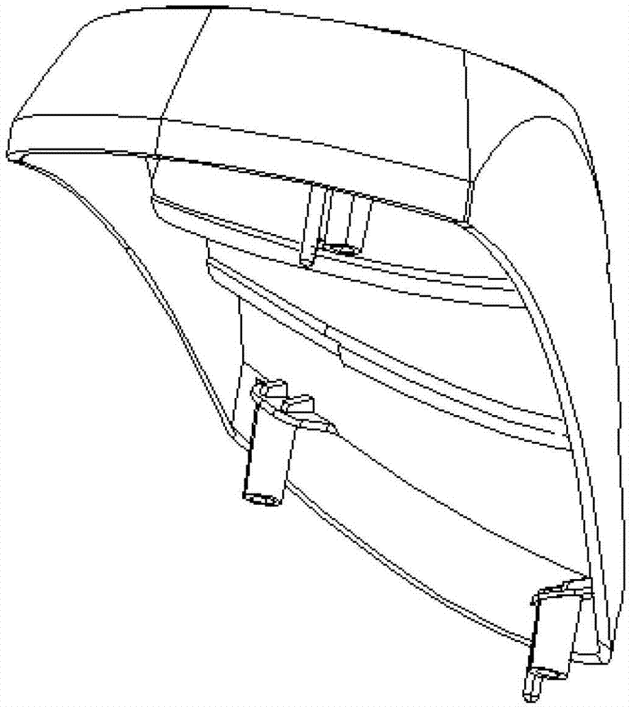
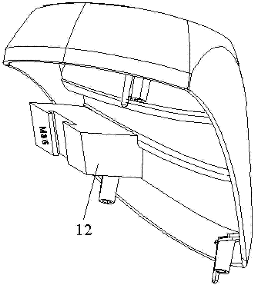
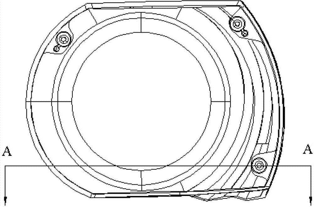
[0016] Such as Figures 2 to 5 As shown, a mechanical inner core-pulling mold includes a lower push plate 1, a lower push rod fixing plate 2, an upper push plate 3 and an upper push rod fixing plate 4, and the lower push rod is sequentially installed on the lower push plate 1 to fix Plate 2, upper push plate 3 and upper push rod fixing plate 4, the four corners of the lower push plate 1, lower push rod fixing plate 2, upp...


PUM


Abstract

The invention relates to a mechanical internal-core-pulling mould including a lower push plate, a lower push-rod fixing plate, an upper push plate and an upper push-rod fixing plate, the lower push-rod fixing plate, the upper push plate and the upper push-rod fixing plate are sequentially arranged on the lower push plate, limit connection rods are arranged at the positions of the four vertex angles of the lower push plate, the lower push-rod fixing plate, the upper push plate and the upper push-rod fixing plate, a pad plate and a move mould plate are sequentially arranged above the upper push-rod fixing plate, the four vertex angles of the pad-plate and the move mould plate are arranged on the limit connection rods, springs are arranged between the pad-plate and the upper push-rod fixing plate, and each limit connection rod is sleeved by one spring, a connecting rod is arranged at the side edge of the move mould plate in a hinged connection mode, the connecting rod is vertically arranged, the upper end of the connecting rod is provided with a slant slide rail, the lower end of the connecting rod passes through the pad plate and penetrates into an installing hole of the upper push-rod fixing plate, an internal pulling core is arranged on the slide rail of the upper end of the connecting rod, and the internal pulling core is provided with a slant dovetail groove matched with the slide rail. According to the mechanical internal-core-pulling mould, the internal pulling core having the slant dovetail groove is connected to the connecting rod having the slant slide rail, and mechanical power is transmitted by the mechanical structure to realize core pulling.

Description

technical field [0001] The invention belongs to the technical field of injection molds, in particular to a mechanical inner core-pulling mold. Background technique [0002] There are ribs and undercut slopes in the undercut area of ​​injection molded parts (such as figure 1 For the injection molded parts shown in ), an internal core-pulling mechanism is required on the mold to solve the problem of product ejection. In the prior art, the core-pulling generally uses an oil cylinder as the power, but if the core-pulling cylinder is used, the mold will be disassembled and repaired. The hydraulic oil in the oil cylinder is easy to splash onto the molding area of ​​the mold core. Since the product needs to be aluminum-plated after molding, the surface of the mold core forming area is polished to a mirror surface, so it is difficult to remove the hydraulic oil. Once there is hydraulic oil remaining on the surface of the molding area, it will cause Defective aluminum plating. Ther...

Claims


Application Information

Patent Timeline
Patent Type & Authority Patents(China)
IPC IPC(8): B29C45/33B29C45/40
Inventor 练子宏
Owner KUSN TUOAN PLASTIC PRODS
Why Eureka
Try Eureka