
Bake frying machine

A frying machine and baking pan technology, applied in frying pans, household appliances, applications, etc., can solve the problems of discontinuous screw adjustment, power consumption, unsightly electric baking pans, etc., to reduce the loss of heat and food moisture, Easy to package and store, simple and reasonable structure

Active Publication Date: 2013-10-30
MIDEA GRP CO LTD
View PDF14 Cites 23 Cited by
  • Summary
  • Abstract
  • Description
  • Claims
  • Application Information

AI Technical Summary

Problems solved by technology

Claim 1 of this patent discloses that the upper baking pan and the upper cover shell can perform piston-type movement, but the structure and connection relationship of the fast-acting control screw are incomplete and unclear
However, according to the manual, the fast-moving screw and nut have two states of misalignment and alignment. According to this description, the adjustment of the screw is discontinuous. In actual use, the alignment can only be adjusted, which will bring some inconvenience to the user.
At the same time, the part of the screw rod exposed to the upper cover shell is longer, which makes the whole electric baking pan look very unattractive, requires a large space for packaging, and is not convenient for users to store
In addition, the solution is to realize the suspension of the upper cake pan, and it is necessary to add a mechanism in the upper cover shell, which makes the user consume more force when opening the cover.

Method used


Image

  • Bake frying machine
  • Bake frying machine
  • Bake frying machine

Examples


Embodiment 1

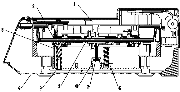
[0029] Such as figure 1 with figure 2 As shown, a grilling machine includes an upper shell assembly 1, an upper grill assembly 2, a lower grill assembly 3, and a lower shell assembly 4. The upper grill assembly 2 is placed in the upper shell assembly 1, and the lower grill assembly The disk assembly 3 is placed in the lower housing assembly 4, and the upper housing assembly 1 and the lower housing assembly 4 are hinged at one end and buckled at the other end to form a cavity with a fixed height.

[0030] Such as Figure 4 with Figure 5 As shown, the bottom of the lower baking pan assembly 3 is fixed with a guide post 8, and the bottom of the lower housing assembly 4 is fixed with a guide sleeve 9. The guide post 8 can slide freely and smoothly in the guide sleeve 9, and is a clearance fit. The outer side of the guide sleeve 9 is covered with a spring 5 , the lower end of the spring 5 is supported on the lower shell assembly 4 , and the upper end of the spring 5 is support...

Embodiment 2

[0036] A grilling machine, comprising an upper shell assembly (not shown in the figure), a lower shell assembly 4 , an upper grill assembly (not shown in the figure), and a lower grill assembly 3 . Wherein the upper grill assembly is placed in the upper shell assembly, and the lower grill assembly 3 is placed in the lower shell assembly 4 . Such as Image 6 , Figure 7As shown, the lifting device in this embodiment is a screw pair and a gear 12; the screw pair includes a screw 11 and a screw nut 16, wherein the screw 11 is fixed on the bottom of the lower baking pan assembly 3, and the lower baking pan assembly 3 Floating up and down, the screw nut 16 is fixed in the lower housing assembly 4, and the gear 12 is installed in the lower housing assembly 4 so as to be horizontally rotatable. The gear 12 includes a driving disc 122 and an adjusting disc 121, and the gear driving disc 122 meshes with the screw nut 16 , a portion of the adjusting disc 121 is exposed from the lower ...

Embodiment 3

[0039] The basic structure of this embodiment is the same as that of Embodiment 2, the difference is that Figure 8 As shown, the lifting device in this embodiment is a rack 13 and a gear 14 arranged between the lower shell assembly 4 and the lower grill assembly 3; the rack 13 is vertically arranged, and its top end is fixed on the bottom of the lower grill assembly 3 The gear 14 is axially rotatably installed in the lower housing assembly 4, and the gear 14 meshes with the rack 13. The rotation of the gear 14 can drive the rack 13 to move up and down, thereby realizing the floating of the lower grill assembly 3 up and down. The center of the gear protrudes from the adjustment rod, and the adjustment rod is exposed from the side of the lower housing assembly.


PUM


Abstract

The invention discloses a bake frying machine which comprises an upper shell assembly, an upper baking tray assembly, a lower baking tray assembly and a lower shell assembly. The upper baking tray assembly is arranged in the upper shell assembly, the lower baking tray assembly is arranged in the lower shell assembly, one end of the upper shell assembly is hinged to one end of the lower shell assembly, and the other end of the upper shell assembly and the other end of the lower shell assembly are fastened to form an internal closed cavity; a lifting device which can drive the baking tray assemblies to move is further arranged in the cavity. The bake frying machine has the advantages that the bake frying machine is additionally provided with the lifting device, so that the upper baking tray assembly or the lower baking tray assembly can be suspended in a shell, the upper shell assembly and the lower shell assembly which are fastened together cannot be opened as long as the thickness of food is within a suspension displacement variation range of two baking surfaces, and accordingly loss of heat and loss of moisture of the food are greatly reduced.

Description

[0001] technical field [0002] The invention belongs to the technical field of grilling machines, and in particular relates to a grilling machine in which a grill pan can be suspended in a casing. Background technique [0003] The frying machine or the electric baking pan heats the food at the same time through the upper and lower baking pans, which saves the time for the food to be fully cooked and reduces the user's action of turning the food, so it is accepted by more users. The upper and lower baking pans of a traditional frying machine are fixedly connected to the upper shell assembly and the lower shell assembly respectively. The body assembly and the lower shell assembly are designed in the form of floating hinges. [0004] But when cooking thick food, the upper baking tray and the upper casing assembly are raised together, so that the original airtight fastening surfaces of the upper casing assembly and the lower casing assembly are separated, resulting in a larger...

Claims


Application Information

Patent Timeline
Patent Type & Authority Applications(China)
IPC IPC(8): A47J37/10
Inventor 田康赵国尧杜明辉吴坚
Owner MIDEA GRP CO LTD
Learn More