
Method and apparatus for forming a translating multifocal contact lens

A contact lens, translation technology, used in lenses, applications, household appliances, etc., can solve problems such as wearing discomfort

Active Publication Date: 2016-12-28
JOHNSON & JOHNSON VISION CARE INC
View PDF12 Cites 0 Cited by
  • Summary
  • Abstract
  • Description
  • Claims
  • Application Information

AI Technical Summary

Problems solved by technology

Another disadvantage of the prior art is the discomfort when worn on the eye

Method used


Image

  • Method and apparatus for forming a translating multifocal contact lens
  • Method and apparatus for forming a translating multifocal contact lens
  • Method and apparatus for forming a translating multifocal contact lens

Examples


Embodiment Construction

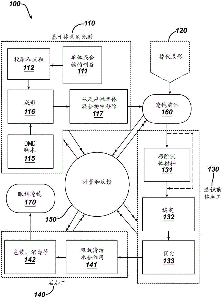
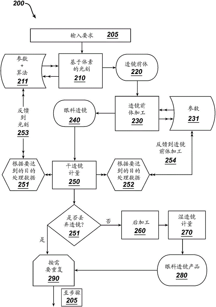
[0062] Described herein is a translating multifocal contact lens comprising one or both of a lower eyelid contact surface and a lower eyelid support structure according to patient-specific eye data, and method steps and apparatus for implementing them. The lenses described herein may include free-form, translating multifocal contact lenses, as discussed more fully below with reference to the various figures.

[0063] In the following sections, detailed descriptions of embodiments of the present invention are given. DESCRIPTION OF PREFERRED AND ALTERNATIVE EMBODIMENTS Although presented herein as examples only, those skilled in the art will appreciate that alterations, changes and modifications may be apparent. Therefore, it should be understood that the described examples do not limit the breadth of the aspects of the underlying invention. The method steps described herein are presented in logical order in this discussion. However, the order in no way limits the order in whi...


PUM


Abstract

A translating multifocal contact lens comprising multiple optic zones and a lower eyelid contact surface is described, along with method steps and apparatus for implementing them. The lens may optionally include a lower eyelid support structure. At least a portion of one surface of the translating multifocal lens may be free-form, including the lower eyelid contact surface and optional lower lid support structure capable of constraining the lens as the eye changes from one optical zone to another. The amount of translation across the surface of the eye.

Description

technical field [0001] This invention relates to contact lenses. More specifically, the present invention relates to a translating multifocal contact lens comprising multiple optic zones and one or both of a lower lid support structure and a lower lid contact structure, wherein when the eye is between the multiple optic zones The structure assists in limiting the movement of the lens over the eye during translation. Background technique [0002] Bifocal lenses include two or more zones or zones of differing light intensities, usually including a distance vision optic zone for distance vision and a near vision optic zone for near or very near vision. The two zones may be subdivided into additional vision zones, in which case the lens may be referred to as a multifocal lens. Previously known multifocal lenses have been limited by known production means such as cast molding, standard extrusion or iron-on techniques and injection molding techniques. [0003] The retinal image...

Claims


Application Information

Patent Timeline
Patent Type & Authority Patents(China)
IPC IPC(8): G02C7/04G02C7/06
CPCB29D11/00144B29C35/0805G02C7/043G02C7/048B29D11/00028B29C2035/0833B29C2071/0027B29D11/00153G02C7/04G02C7/06G02B3/10B29D11/00038B29D11/00057
Inventor C.维尔德史密斯M.F.维曼J.P.亚当斯
Owner JOHNSON & JOHNSON VISION CARE INC
Learn More