
Printer control method and printer

A technology of a printing device and a control method, applied in the directions of printing device, printing, etc., can solve the problems of loss of suction pressure, inability to obtain sufficient suction pressure, and ink flight deviation.

Inactive Publication Date: 2013-10-23
SEIKO EPSON CORP
View PDF7 Cites 9 Cited by
  • Summary
  • Abstract
  • Description
  • Claims
  • Application Information

AI Technical Summary

Problems solved by technology

[0005] In the above-mentioned Patent Document 1, for example, even when using a narrow recording paper, the suction hole on the outside of the recording paper is opened to perform air suction, so a sufficient suction pressure cannot be obtained due to loss of suction pressure.
[0006] In addition, if there is a suction hole in the outer region of the front end of the recording paper, droplets such as ink will be sucked and the flying deviation will occur, so that good printing quality cannot be obtained.

Method used


Image

  • Printer control method and printer
  • Printer control method and printer
  • Printer control method and printer

Examples


Embodiment Construction

[0037] Hereinafter, embodiments of the present invention will be described with reference to the drawings.

[0038] In addition, the drawings referred to in the following description are schematic diagrams in which the vertical and horizontal scales of each member and part are different from the actual size in order to make each member a recognizable size.

[0039] (printing device, overall configuration)

[0040] The printing device described in this embodiment exemplifies a roll paper printer having a suction mechanism for sucking recording paper to the platen.

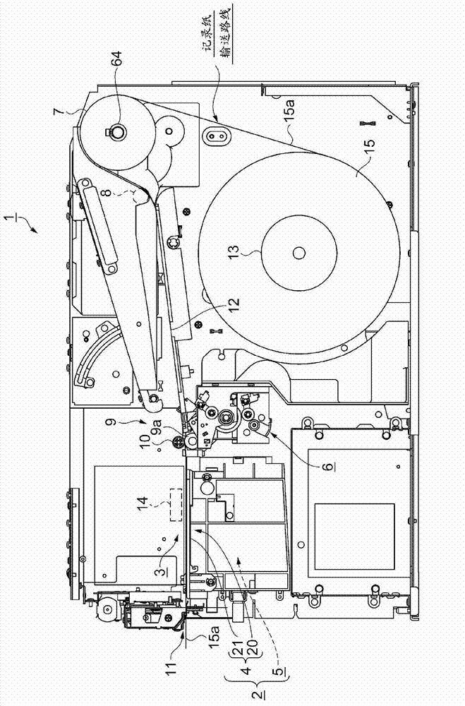
[0041] figure 1 It is an explanatory diagram showing the overall configuration of the inside of the printing apparatus according to this embodiment. The printing device 1 includes a main body of the printing device and a recording paper conveying unit as main components.

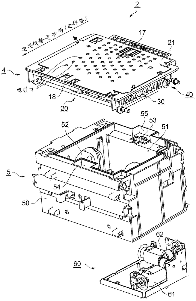
[0042] The main body of the printing device includes: a liquid droplet ejection head 3; a platen unit 2, which is arranged to face the liquid ...


PUM


Abstract

A printer has a fluid ejection head, an opening / closing mechanism that is disposed opposite the inkjet head, and suction holes arrayed in the conveyance direction of the recording paper, and opens and closes the suction holes. A printer control method has steps of detecting the position of the leading end of the recording paper before starting conveyance of the recording paper; reading the next recording paper conveyance speed Vpf; calculating a delay time Td1 for starting the opening / closing mechanism after recording paper conveyance starts based on the position of the leading end of the recording paper and the recording paper conveyance speed Vpf; determining the time when the opening / closing mechanism starts operating based on the delay time Td1; and starting the opening / closing mechanism at the start time and opening the suction holes.

Description

technical field [0001] The present invention relates to a control method of a printing device and a printing device controlled using the control method. Background technique [0002] In a printer that ejects ink droplets from an ink ejection head to print on recording paper, from the viewpoint of ensuring print quality, the recording paper is closely attached to the platen surface that specifies the printing position for the recording paper to accurately print. It is important to ensure platen clearance. In such a case, in order to convey the recording paper in close contact with the platen surface, a suction platen is used that conveys the recording paper while sucking the recording paper to the platen surface by air. However, if the suction pressure is low, the recording paper may float and cause Problems such as deterioration of print quality and ink contamination caused by rubbing of recording paper against the ink ejection head. [0003] Then, there is known a printin...

Claims


Application Information

Patent Timeline
Patent Type & Authority Applications(China)
IPC IPC(8): B41J15/04B41J2/01B41J29/38
CPCB41J11/0085B41J11/06B41J13/0009
Inventor 石森浩之
Owner SEIKO EPSON CORP
Learn More