
Optical cable assembly connector

An optical cable assembly and connector technology, applied in the field of optical cable assembly connectors, can solve the problems of limited battery life, large size of hot-melt equipment, expensive fusion splicer, etc., and achieves light weight, simple structure, and good high and low temperature resistance performance. Effect

Inactive Publication Date: 2013-10-16
SHANDONG INTELLIGENT OPTICAL COMM DEV
View PDF5 Cites 15 Cited by
  • Summary
  • Abstract
  • Description
  • Claims
  • Application Information

AI Technical Summary

Problems solved by technology

[0002] The connection of traditional optical fiber cables can only rely on hot-melt splicing, but hot-melt connection has certain limitations: 1. The construction of the hot-melt machine requires an operating platform, and the space is limited; 2. The fusion splicer is expensive and the construction cost is high; 3. Active construction, limited battery life; 4. Hot-melt equipment is bulky and inconvenient to carry; fast connection of optical cables is an important part of the development of optical communication technology. Now the general optical cable connectors are FC, LC, SC, ST, D4, DIN, MU, MT, etc., can only carry out one-way information transmission of optical cables

Method used


Image

  • Optical cable assembly connector
  • Optical cable assembly connector

Examples


Embodiment Construction

[0042] The principles and features of the present invention are described below in conjunction with the accompanying drawings, and the examples given are only used to explain the present invention, and are not intended to limit the scope of the present invention.

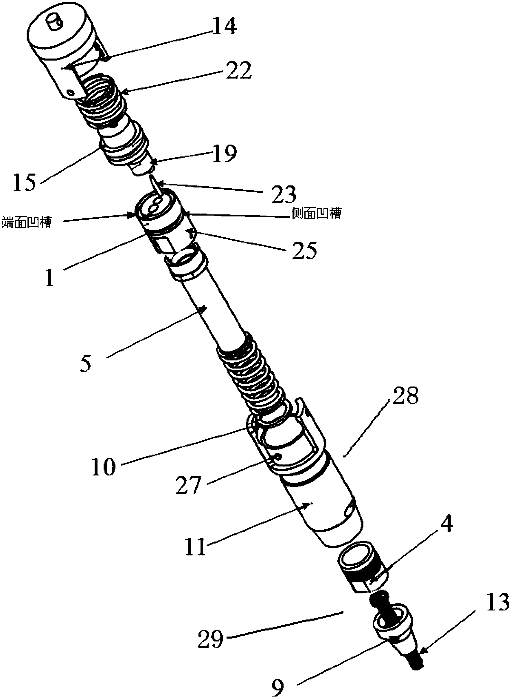
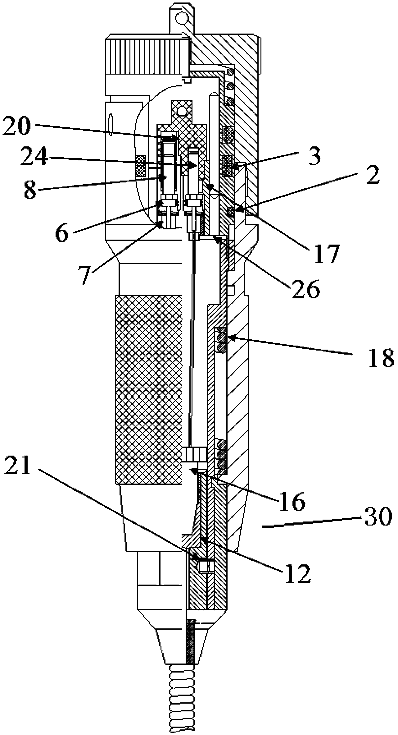
[0043] Such as figure 1 , 2 As shown, it is an optical cable assembly connector described in Embodiment 1 of the present invention, including a plug body 1, a housing 28, an optical cable access device 29 and an optical cable locking device 30;

[0044] One end of the plug body 1 is connected to the housing, and the other end of the plug body 1 is used to connect with other plug bodies;

[0045] One end of the housing 28 is connected to the plug body 1, and the other end is connected to the optical cable access device 29, and the housing 28 transports the optical cable inserted from the optical cable access device 29 to the plug body 1;

[0046] One end of the optical cable access device 29 is connected to the hou...


PUM


Abstract

The invention relates to an optical cable assembly connector which comprises a plug body, a housing, an optical cable access apparatus and an optical cable locking apparatus. One end of the plug body is connected with the housing, and the other end of the plug body is used for connecting with other plug bodies. One end of the housing is connected with the plug body and the other end of the housing is connected with the optical cable access apparatus. The housing conveys an optical cable accessed from the optical cable access apparatus. One end of the optical cable access apparatus is connected with the housing, and the other end of the optical cable access apparatus is used for receiving the inserted optical cable and conveying the optical cable to the housing. The optical cable locking apparatus is disposed at a joint of the housing and the optical cable access apparatus, and is used for fixing the connection between the housing and the optical cable access apparatus and locking the optical cable inside the housing and the optical cable access apparatus. The optical cable assembly connector realizes ensures simultaneous rapid connection between two optical fibers and simultaneous reception and transmission of optical signals, is relatively good in quality of optical signal transmission, and can satisfy use demands of different users.

Description

technical field [0001] The invention relates to an optical cable assembly connector for realizing fast connection of optical cables, and belongs to the technical field of optical communication technology development. Background technique [0002] The connection of traditional optical fiber cables can only rely on hot-melt splicing, but hot-melt connection has certain limitations: 1. The construction of the hot-melt machine requires an operating platform, and the space is limited; 2. The fusion splicer is expensive and the construction cost is high; 3. Active construction, limited battery life; 4. Hot melt equipment is bulky and inconvenient to carry; realizing fast connection of optical cables is an important part of the development of optical communication technology. Now the general optical cable connectors are FC, LC, SC, ST, D4, DIN, MU, MT, etc., can only carry out one-way information transmission of optical cables. Contents of the invention [0003] The technical pr...

Claims


Application Information

Patent Timeline
Patent Type & Authority Applications(China)
IPC IPC(8): G02B6/38G02B6/44
Inventor 岳跃宾高剑强柏立民顾学理吴振坤
Owner SHANDONG INTELLIGENT OPTICAL COMM DEV
Learn More