
Special ground conducting wire hydraulic compression connector for transmission line

A technology of power transmission lines and ground wires, which is applied in the direction of connection and connection by deformation, connection/termination of cables, etc., which can solve the problem that it is difficult to ensure the long-term safe use of crimping points, no public patent documents have been found, and the quality of righting cannot be guaranteed, etc. Problems, to achieve reliable crimping, low cost and high precision

Active Publication Date: 2013-10-02
STATE GRID CORP OF CHINA +1
View PDF4 Cites 7 Cited by
  • Summary
  • Abstract
  • Description
  • Claims
  • Application Information

AI Technical Summary

Problems solved by technology

At present, when using the existing hydraulic device for crimping, it is necessary to manually support the wire, and determine the level of the wire according to the feel, so the quality of the straightening cannot be guaranteed, and the problem of straightening with a manual mallet has to be used, which not only affects the work efficiency, but also It is also difficult to guarantee the long-term safe use of crimping points
[0003] Through searching, no published patent documents identical with the application of the present invention have been found

Method used


Image

  • Special ground conducting wire hydraulic compression connector for transmission line
  • Special ground conducting wire hydraulic compression connector for transmission line
  • Special ground conducting wire hydraulic compression connector for transmission line

Examples


Embodiment Construction

[0018] In order to further understand the content, characteristics and effects of the present invention, the following examples are given, and detailed descriptions are given below with reference to the accompanying drawings. It should be noted that this embodiment is descriptive, not restrictive, and cannot thereby limit the protection scope of the present invention.

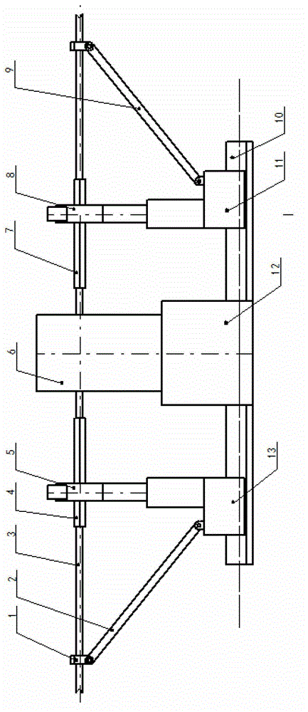
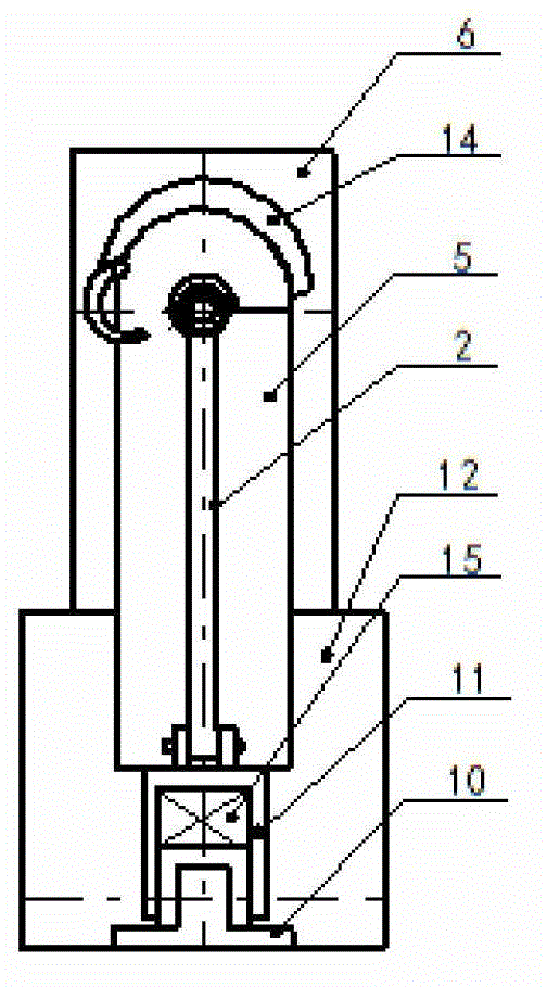
[0019] A hydraulic crimping device for ground wires dedicated to power transmission lines, including hydraulic clamps 6, left clamps 5, right clamps 8, left lifting rods 2, right lifting rods 9 and channel steel guide rails 10, the hydraulic clamps pass through the positioning seat 12 Positioning is installed in the middle of the channel steel guide rail, and the left and right clamps are symmetrically arranged on the left and right sides of the hydraulic pliers. Sliding operation, the mounting holes made by the left jig, hydraulic pliers and right jig are on the same axis. Bearing 15 is all installed between ...


PUM


Abstract

The invention relates to a special ground conducting wire hydraulic compression connector for a transmission line, which comprising a hydraulic plier, a left fixture, a right fixture, a left supporting-holding rod, a right supporting-holding rod and a channel steel guide rail, wherein the hydraulic plier is mounted in the middle of the channel steel guide rail in a positioning manner through a positioning base; the left fixture and the right fixture are symmetrically arranged on the left side and the right side of the hydraulic plier, and operate in a sliding manner respectively through a left tackle and a right tackle both sliding on the channel steel guide rail; mounting holes respectively manufactured by the left fixture, the hydraulic plier and the right fixture are on the same axis; the left supporting-holding rod and the right supporting-holding rod are hinged to the left tackle and the right tackle respectively in a mirror symmetry manner. According to the invention, the special ground conducting wire hydraulic compression connector is advanced in construction and simple to operate, can be suitable for the application of various compression connection tubes after a horizontal mid-partition limiting aluminium pipe is adopted, has high precision for horizontally compressing and connecting butted steel connecting pipes and connecting aluminium pipes, can support and hold aluminium conducting wires per se, automatically completes the straightening of ground conducting wires, completely avoids various problems existing in the manual compression and connection, and has the advantages that the compressing connection is reliable, the precision is high and the cost is low.

Description

technical field [0001] The invention belongs to the field of electric power, and relates to a ground wire connection of a power transmission line, in particular to a hydraulic crimping device for a ground wire dedicated to a power transmission line. Background technique [0002] In the construction process of overhead transmission lines, hydraulic crimping of the ground wire is widely used for the connection of the ground wire. Since the ground wire needs to be buried after connection, it is an important concealed project, which is related to the engineering quality of the transmission line and the long-term safe operation of the power grid. At present, when using the existing hydraulic device for crimping, it is necessary to manually support the wire, and determine the level of the wire according to the feel, so the quality of the straightening cannot be guaranteed, and the problem of straightening with a manual mallet has to be used, which not only affects the work efficie...

Claims


Application Information

Patent Timeline
Patent Type & Authority Applications(China)
IPC IPC(8): H02G1/14H01R43/04
Inventor 饶友平黄磊王树贵
Owner STATE GRID CORP OF CHINA
Learn More