
Tail lamp with replaceable mirror and adjustable lamp angle

A lens and lamp body technology, which is applied to the parts of lighting devices, lighting devices, motor vehicles, etc., can solve the problems of various user selectivity restrictions, different requirements for irradiation angles, and increased user costs, achieving low implementation costs , Simple, reasonable and compact structure, easy installation

Inactive Publication Date: 2013-09-25
余德锐
View PDF3 Cites 2 Cited by
  • Summary
  • Abstract
  • Description
  • Claims
  • Application Information

AI Technical Summary

Problems solved by technology

However, the actual laser projection image of bicycle taillights is relatively single. When users want to change to another projection pattern, they must re-purchase projection laser taillights. This will undoubtedly increase the user's cost of use, and the user's diverse options are limited to a certain extent.
[0003] At the same time, the angle of the light body in the traditional technology is not adjustable. When the taillight is installed on the bicycle tube, the illumination angle of the taillight is fixed, but the illumination angle requirements of different users may be different, which gives the user brought certain troubles, therefore, the taillights in the traditional technology still need to be further improved

Method used


Image

  • Tail lamp with replaceable mirror and adjustable lamp angle
  • Tail lamp with replaceable mirror and adjustable lamp angle
  • Tail lamp with replaceable mirror and adjustable lamp angle

Examples


Embodiment Construction

[0024] The present invention will be described in further detail below with reference to the accompanying drawings and embodiments.

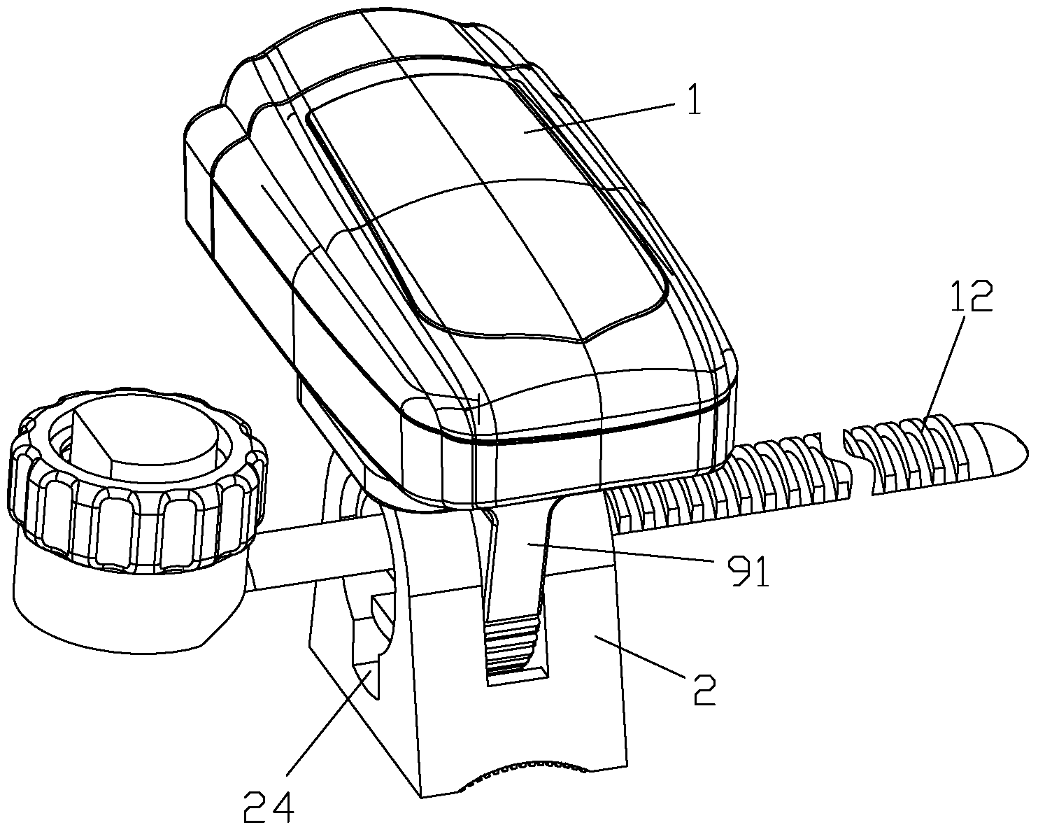
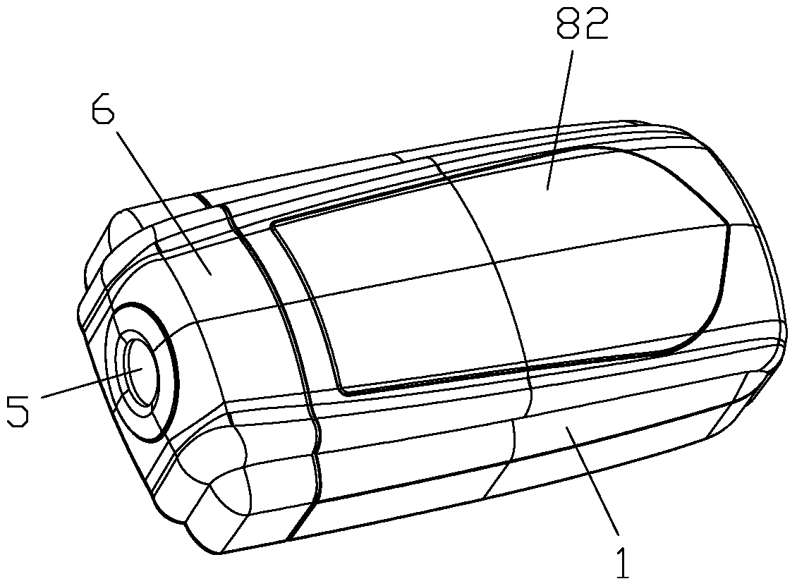
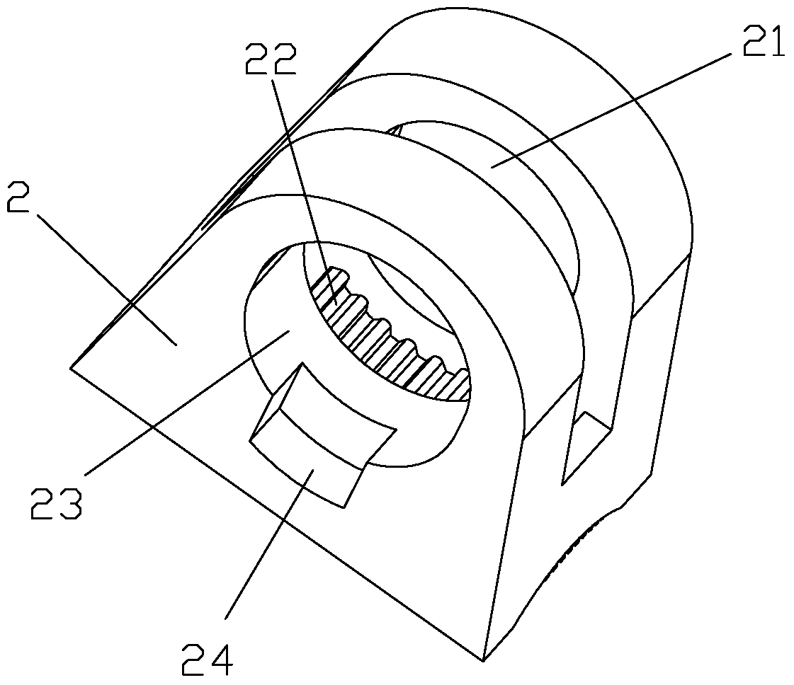
[0025] refer to Figure 1~Figure 8 , a tail light with replaceable lenses and adjustable lamp body angle of the present invention includes a lamp body 1 and a base 2, the base 2 can be fixed on the bicycle tube through a structure such as a clamp, and the front end of the lamp body 1 A laser head 3 is provided, a lens rubber sleeve 4 is set on the laser head 3, a lens 5 is installed in the lens rubber sleeve 4, and a cover 6 is installed on the front of the lamp body 1 to cover the lens rubber sleeve 4. It is shielded from the laser head 3, and a laser through hole 61 is provided on the cover 6 to give way to the laser.

[0026] In this embodiment, the inner wall of the lens rubber sleeve 4 is provided with protrusions 41 for clamping the lens 5 in the circumferential direction.

[0027] As a preferable example of the embodiment of the present...


PUM


Abstract

The invention discloses a tail lamp with a replaceable mirror and adjustable lamp angle. The tail lamp comprises a lamp body and a base, wherein the front end of the lamp body is provided with a laser emitter. A mirror rubber sleeve is sleeved on the laser emitter. A mirror is mounted in the mirror rubber sleeve. An enclosure for shielding the mirror rubber sleeve and the laser emitter is mounted in the front of the lamp body. The enclosure is provided with a laser through hole allowing laser to pass through. The tail lamp further comprises a connecting block fixed on the base. The lower portion of the connecting block is in a gear structure. The base is provided with a gap. The lower portion of the connecting block is inserted into the gap before a gear on the lower portion of the connecting block is meshed with gear teeth at the bottom of the gap. The base is provided with a through hole which is coaxial with the lower portion of the connecting block. The connecting block is fixed on the base through a pin which passes through the through hole and a shaft hole of the lower portion of the connecting block, and the pin is in loose fit with the shaft hole of the lower portion of the connecting block and is fixedly connected with the base. The tail lamp has the advantages that the mirror is convenient to replace and the lamp body is convenient to adjust.

Description

technical field [0001] The invention relates to a taillight, in particular to a laser taillight with a replaceable lens and an adjustable angle of the lamp body, which is used for outdoor sports riding projection. Background technique [0002] The current use value of bicycles is not only as a means of transportation. With the improvement of living standards, people need green sports to exercise, and bicycles just respond to people's needs and reproduce people's role as a very important green exercise tool. In life, urban people are busy, and people usually start in the evening when they ride, so night riding is completely more prominent. Bicycle taillights are one of the necessary installation equipment. However, the actual laser projection image of the bicycle tail light is relatively simple. When the user wants to change another projection pattern, he must re-purchase the projected laser tail light, which will undoubtedly increase the user's cost of use, and the user's di...

Claims


Application Information

Patent Timeline
Patent Type & Authority Applications(China)
IPC IPC(8): F21V17/00F21V21/14F21W101/023F21W107/13
Inventor 余德锐
Owner 余德锐
Learn More