
Air control system for power take-off with single-h control and its application method

An air control system and power take-off technology, which is applied in the direction of tilt-bearing moving vehicles, etc., can solve the problems of low practicability and can not ensure safe driving power take-off, etc. The effect of safe parking

Active Publication Date: 2015-08-12
DONGFENG MOTOR CORP HUBEI
View PDF5 Cites 0 Cited by
  • Summary
  • Abstract
  • Description
  • Claims
  • Application Information

AI Technical Summary

Problems solved by technology

[0006] The purpose of the present invention is to overcome the defects and problems existing in the prior art that cannot ensure safe driving power taking and low practicability, and provide a driving driving power taking device that can ensure safe driving power and have high practicability. Air control system for power take-off controlled by single H and its application method

Method used


Image

  • Air control system for power take-off with single-h control and its application method

Examples


Embodiment 1

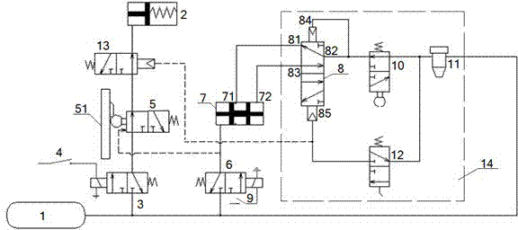
[0044] A single H-operated power take-off pneumatic control system capable of taking power from vehicles, including air reservoir 1, power take-off 2, power take-off solenoid valve 3, power take-off switch 4, low gear control valve 5, parking solenoid valve 6, The middle cylinder 7, the parking switch 9, the high-end shielding valve 13 and the rear auxiliary box single H control system 14. The rear auxiliary box single H control system 14 includes a single H valve 8, a stop valve 10, a pressure limiting valve 11 and a handle control valve 12;

[0045] The air reservoir 1 communicates with the air inlet of the power take-off 2 after passing through the power take-off solenoid valve 3, the low-range control valve 5, and the high-end shielding valve 13 (the air inlet of the power take-off 2 and the control of the power take-off 2 The rod cavity of the cylinder is connected), the output shaft of the power take-off 2 is connected with the gear pump; the air reservoir 1 is connected to...


PUM


Abstract

The invention relates to a single-H operated power takeoff pneumatic control system capable of carrying out traveling power take-off. The electrical control system comprises a gas storage cylinder which is communicated with a gas inlet of a power takeoff after sequentially passing through a power take-off electromagnetic valve and a high-gear shielding valve and meanwhile is communicated with a single-H valve in a rear auxiliary box single-H control system after sequentially passing through a stop electromagnetic valve and a neutral position cylinder; a gas outlet of the stop electromagnetic valve is communicated with a control port of a low-gear control valve; the coil of the stop electromagnetic valve is connected in series with a stop switch; in the traveling power take-off process, the low-gear control switch ensures that a vehicle can take off power only at the low gear; and in the stop power take-off process, the vehicle is stopped by the stop electromagnetic valve and the low-gear control switch is closed to conduct the power take-off electromagnetic valve so as to carry out stop power take-off. By the design, not only the sudden hoisting phenomenon can be avoided, but also traveling power take-off and stop power take-off can be safely carried out.

Description

Technical field [0001] The invention relates to a power take-off control system for a dump truck, in particular to a single H-operated power take-off pneumatic control system capable of taking power from a vehicle and a method of use thereof, and is particularly suitable for avoiding sudden lifting and being safe The driving force of the vehicle, the parking force. Background technique [0002] At present, it is common in China that dump trucks suddenly lift up automatically when driving and hit obstacles. This phenomenon often leads to serious traffic accidents, huge economic losses, and even car crashes. Although many OEMs and refitting factories have proposed different preventive measures, they have failed to fundamentally solve such problems. [0003] The Chinese Patent Authorization Announcement Number is CN2837570Y. The utility model patent with the authorized announcement date of November 15, 2006 discloses a pneumatic control device for the hydraulic dumping mechanism of a...

Claims


Application Information

Patent Timeline
Patent Type & Authority Patents(China)
IPC IPC(8): B60P1/16
Inventor 蔚连浩张常武谢浩黄遵国何秀校杨万江
Owner DONGFENG MOTOR CORP HUBEI
Learn More