
Orthogonal basis function set for ditigal predistorter

A technology of predistorter and basis function, which is applied in the direction of improving amplifiers to reduce nonlinear distortion, amplifiers, high-frequency amplifiers, etc., and can solve nonlinear problems

Active Publication Date: 2013-09-11
TELEFON AB LM ERICSSON (PUBL)
View PDF4 Cites 3 Cited by
  • Summary
  • Abstract
  • Description
  • Claims
  • Application Information

AI Technical Summary

Problems solved by technology

However, the response of the amplifier at or near the saturation point is non-linear

Method used


Image

  • Orthogonal basis function set for ditigal predistorter
  • Orthogonal basis function set for ditigal predistorter
  • Orthogonal basis function set for ditigal predistorter

Examples


Embodiment Construction

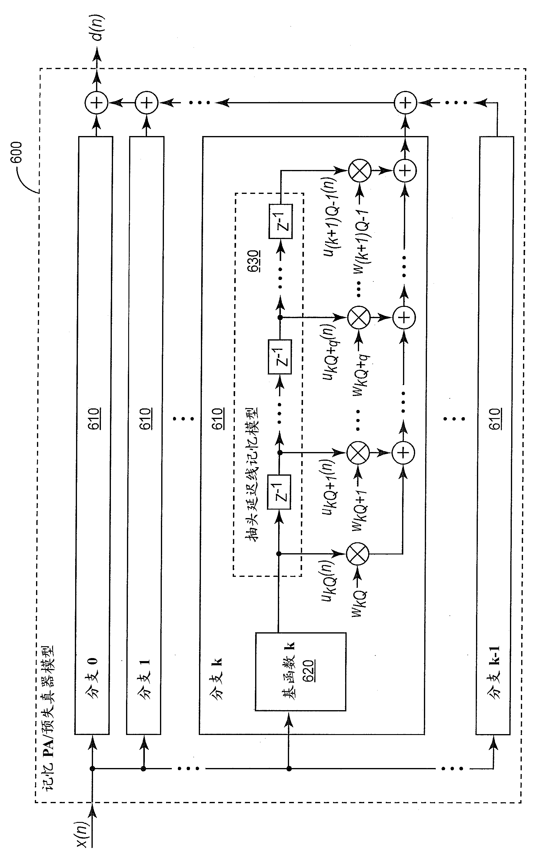
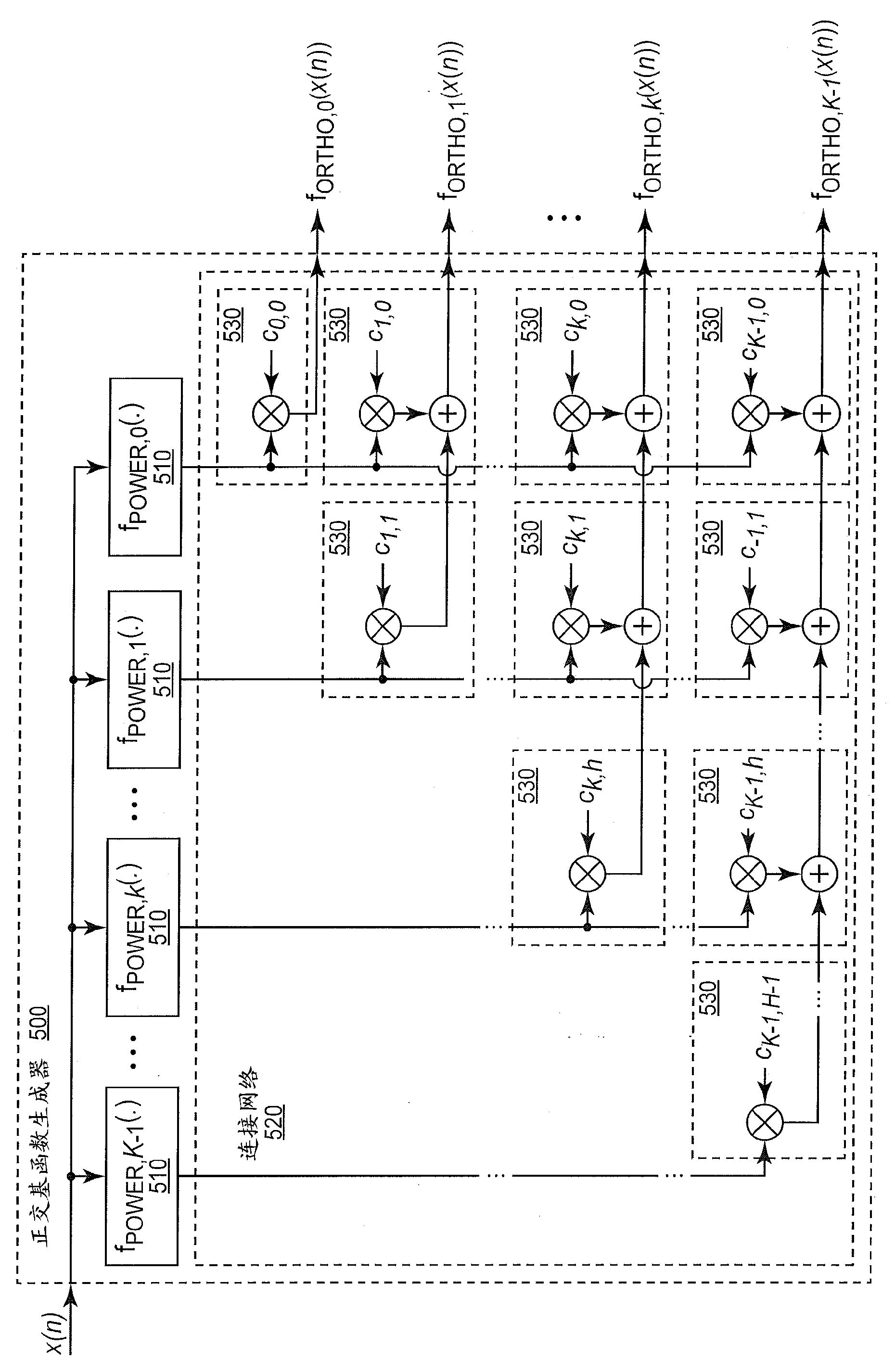
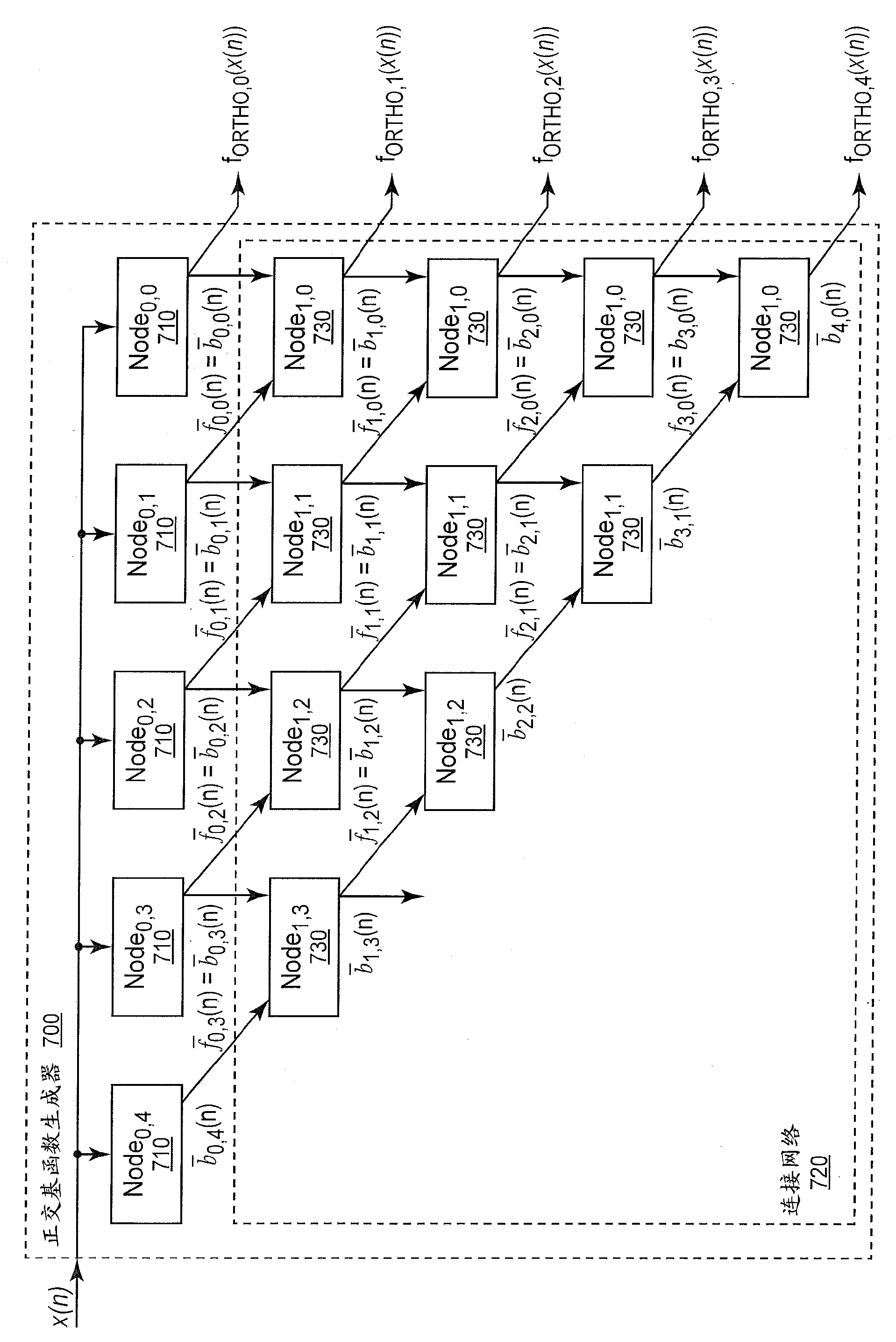
[0021] Referring now to the graph, figure 1 A digital predistortion system 100 configured to compensate for distortion to a communication signal by a power amplifier 120 is shown. Power amplifier 120 is generally most efficient when operating in the non-linear range. However, the non-linear response of the power amplifier 120 causes out-of-band emissions and reduces spectral efficiency in the communication system. The predistorter 110 may be used to improve power amplifier efficiency and linearity by distorting the input signal to the power amplifier 120 to compensate for nonlinear distortion caused by the power amplifier 120 . The cascading of the predistorter 110 and the power amplifier 120 improves the linearity of the output signal and thus allows the power amplifier 120 to operate more efficiently. While predistortion is used in the circuits and systems described herein to linearize the output of power amplifier 120, those skilled in the art will appreciate that the tec...


PUM


Abstract

A predistorter applies a distortion function to an input signal to predistort the input signal. The output of the distortion function is modeled as the sum of the output signals from the orthogonal basis functions weighted by corresponding weighting coefficients. Techniques are described for orthogonalizing the basis function output signals depending on the distribution of the input signal.

Description

Background technique [0001] The present invention relates generally to techniques for building physical models of nonlinear electronic devices, and more particularly to methods and apparatus for compensating input signals for distortions of input signals caused by electronic devices. [0002] The design of radio frequency power amplifiers for communication applications often involves a trade-off between linearity and efficiency. Power amplifiers are generally most efficient when operating at or near their saturation point. However, the response of an amplifier at or near its saturation point is nonlinear. In general, the response of a power amplifier exhibits non-linearity and memory effects when operating in the high efficiency range. [0003] One way to improve the efficiency of a power amplifier and its overall linearity is to digitally predistort the input to the power amplifier to compensate for the distortion caused by the power amplifier. In practice, the input signa...

Claims


Application Information

Patent Timeline
Patent Type & Authority Applications(China)
IPC IPC(8): H03F1/32
CPCH03F1/3247H03F1/3252H03F1/3258H03F3/19H03F3/24H03F2201/3209
Inventor 白春龙
Owner TELEFON AB LM ERICSSON (PUBL)
Learn More