
Ultrasonic probe clamp

An ultrasonic probe and fixture technology, which is applied in the direction of using ultrasonic/sonic/infrasonic waves, material analysis using sonic/ultrasonic/infrasonic waves, measuring devices, etc. Membrane and other problems to achieve the effect of ensuring the stability of scanning and ensuring the effect of water coupling

Active Publication Date: 2013-09-11
CNNC NUCLEAR POWER OPERATION MANAGEMENT
View PDF6 Cites 19 Cited by
  • Summary
  • Abstract
  • Description
  • Claims
  • Application Information

AI Technical Summary

Problems solved by technology

[0004] (1) The clamping size is single, and the probe size cannot be replaced;
[0005] (2) The stability is poor, and the probe fixture is easy to tip over when scanning to the weld;
[0006] (3) Poor water coupling, unable to maintain sufficient water film between the probe and the workpiece

Method used


Image

  • Ultrasonic probe clamp
  • Ultrasonic probe clamp

Examples


Embodiment Construction

[0024] A kind of ultrasonic probe fixture of the present invention is described in detail below in conjunction with accompanying drawing and specific embodiment:

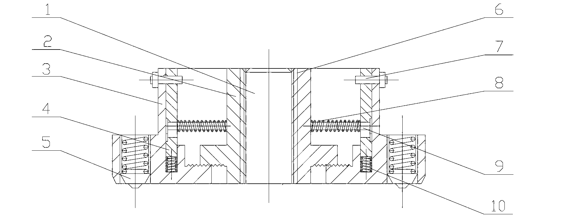
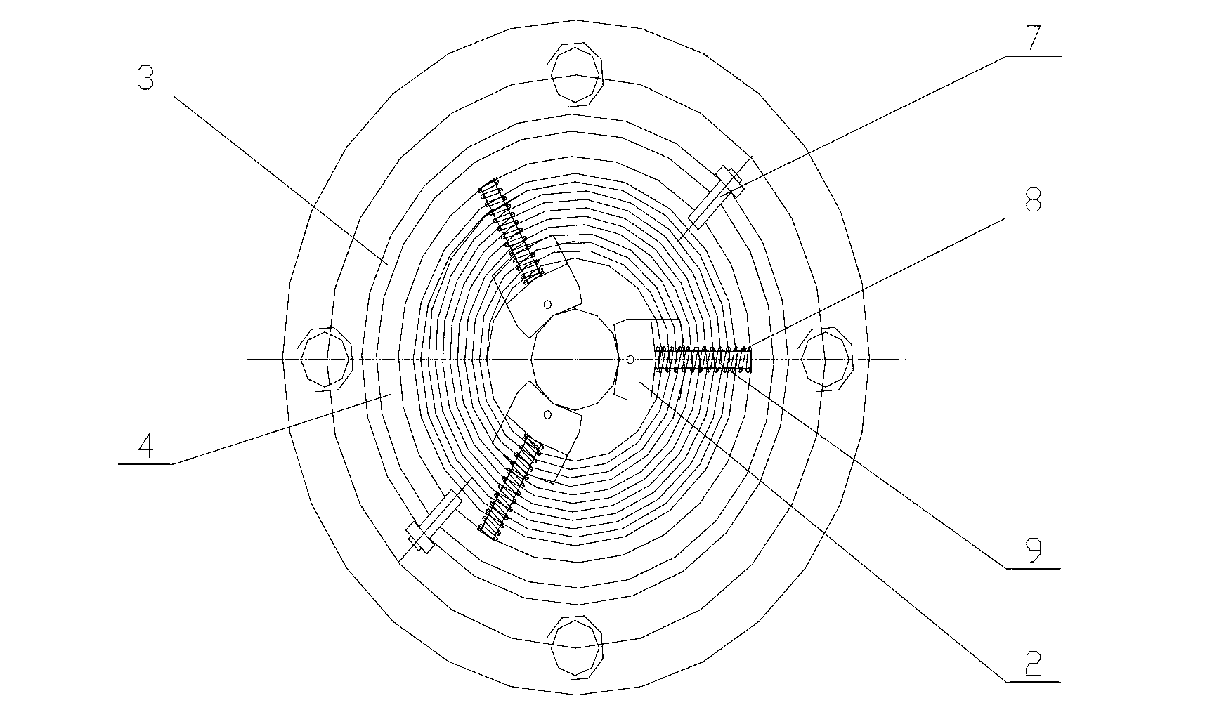
[0025] Such as figure 1 As shown, an ultrasonic probe clamp includes a support block 2 , a clamp inner ring 4 , a base 3 , a spring pin 7 , a support spring 8 , a telescopic rod 9 and a compression spring 10 .

[0026] Wherein, the base 3 is a ring-shaped structure with annular bosses on both sides of the inner and outer sides, and a through hole is opened on the outer boss as a ball roller mounting hole, and the inner boss is stepped, and the inner part of the inner boss is higher than the outer Part 2-3cm, such as 2cm, 2.5cm or 3cm; an annular groove is arranged on the inner part of the inner boss, and a thread is arranged on the top of the outer part of the inner boss. The upper part of the base 3 has a through hole as a spring pin mounting hole for mounting the spring pin 7; generally, there are multiple spring...


PUM


Abstract

The invention belongs to the field of an ultrasonic detection technology in nondestructive testing and particularly relates to an ultrasonic probe clamp. Aiming to solve the problems in the prior art, the invention provides the ultrasonic probe clamp which is applicable to various sizes of probe outer diameters in a range of 12-24mm, is stable to clamp, is stable to scan and is good in coupling. The ultrasonic probe clamp is characterized in that a base (3) is in an annular structure with annular lug bosses at inner and outer sides; a supporting block (2) is in an arc-shaped structure with a lug boss at the lower part; a thread at the bottom of the lug boss of the supporting block (2) is engaged with a thread on the top of an outer side part of the inner side lug loss of the lug bosses of the base (3); a clamp inner ring (4) is mounted on a groove of an inner side part of the inner side lug loss of the base (3). According to the ultrasonic probe clamp, the supporting block 2, the clamp inner ring 4 and the base 3 are adopted; the relative central position of the supporting block 2 can be changed through rotating the clamp inner ring 4, so that a probe can be clamped to randomly adjust the diameter in a range of 12-24mm. The movement of the probe adopts a rolling manner of a roll idler wheel so that the scanning stability is guaranteed. A water inlet hole 6 is adjacent to the probe so as to guarantee the water coupling effect.

Description

technical field [0001] The invention belongs to the technical field of ultrasonic testing in nondestructive testing, and in particular relates to an ultrasonic probe fixture. Background technique [0002] Ultrasonic testing technology is one of the non-destructive testing methods used in the industry. It mainly uses the principle of ultrasonic reflection to detect the position and size of internal defects in the workpiece, and to measure the thickness of the material. Ultrasonic testing requires the surface to be inspected to have a certain degree of smoothness, and the gap between the probe and the surface to be inspected needs to be filled with coupling agent to ensure sufficient acoustic coupling. In order to ensure a good fit between the probe and the surface of the workpiece to be inspected, and to provide a good coupling agent during scanning, it is necessary to use a probe fixture with a certain structure to achieve the above functions. At the same time, considering ...

Claims


Application Information

Patent Timeline
Patent Type & Authority Applications(China)
IPC IPC(8): G01N29/26G01B17/02
Inventor 张维苗学良王东辉于涛丁有元栾兴峰边春华胡明磊余小燕徐科李玉鸣张玲季媛媛桂馨宇
Owner CNNC NUCLEAR POWER OPERATION MANAGEMENT
Learn More